
Target Tracking Experimental System Update - PowerPoint PPT Presentation
1 / 10
Title: Target Tracking Experimental System Update
1
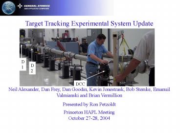
Target Tracking Experimental System
Update Neil Alexander, Dan Frey, Dan Goodin,
Kevin Jonestrask, Bob Stemke, Emanuil Valmianski
and Brian Vermillion Presented by Ron
Petzoldt Princeton HAPL Meeting October 27-28,
2004
2
Progress since June meeting
- Since the UCLA meeting we have
- Modified detectors at station 2 and at the DCC
for increased field of view - Calibrated all detectors (with stationary
stage) - Aligned detectors with target trajectory
- Performed full length (air rifle) testing of
tracking system - Tracked pellets at all three detectors for
vertical position - Tracked pellet arrival times at all three
detectors - Correlated data from all three detector stations
and determined initial position prediction
accuracy
3
Two position measurements are used to predict
final target position ( 14 ?m accuracy required)
Pump
Sabot Removal
Detector Light Source
Potential Flight Paths
Gas Removal
Target
S
a
b
ot
Detector D2
Detector DCC
Detector D1
3.5 m
4.5 m
9 m
DCC measurements are compared to prediction
4
Transverse Position Detection accomplished with
laser illuminated line scan camera
Tracking Detector Assembly
Line Scan Camera
Collimating Lens
Line Generating Laser Diode
Target
1 meter
Axial timing is measured with photodiodes and
time to digital converter
5
We have improved the tracking detectors with a
number of modifications
Timing circuit board
Line scan camera
Detector 1 14 mm FOV
Illuminating lasers
Larger window
Lens
Detector 2, 3 30 mm FOV
Line scan camera
Collimating lens
All three position detector stations are now
operational and working together
6
Detectors were calibrated with translation stages
Repeatability is lt 1 pixel
1 Pixel 6 ?m
Flat field corrected data
Surrogate target
Micrometer
Calibration stages
In use, flat field correction is done
milliseconds prior to each measurement
7
The spherical aberration in our initial setup was
evaluated
25 mm
Target height
Laser
0 mm
Measurements taken in two horizontal positions
10 Pixel 60 micron error
Rays diverge through most of the beam
Spherical aberration can be improved by a more
complex set of optics.next step
8
Pellet arrival times were measured by the
tracking system
Example Data Set
(Insert photo of me firing air rifle)
Surrogate target injector
- Shots taken in air.
- 0.14 speed uncertainty due to aerodynamic
slowing. - Would cause 12 mm axial position prediction error.
9
Pellets were tracked by all three detectors
DCC Tracking (raw data)
sDCC 4.4 mm spred error 2.0 mm
Missing shots were not tracked at all detectors
- Primary causes of prediction error
- Aerodynamic effects on pellet trajectory
- Horizontal effect on vertical position
measurements (spherical aberration) - The air rifle was useful for initial integrated
tracking system testing
10
Summary and Conclusions
- Target tracking and timing systems are
operational and tracking pellets - Steps to improve the position prediction
accuracy - Provide better collimation
- Shoot into vacuum for accurate timing and
ballistic trajectory - Next we will implement the real time position
and timing prediction software
Recommended
CrystalGraphics Presentations


