
Topic 12 Op-Amp Applications - PowerPoint PPT Presentation
1 / 18
Title:
Topic 12 Op-Amp Applications
Description:
Rf is normally = 10 Rin. EDV255 0902 Op-Amp Applications. 4 ... General-class equation An equation derived for a summing ... Determine the Rf / R ratio ... – PowerPoint PPT presentation
Number of Views:450
Avg rating:3.0/5.0
Title: Topic 12 Op-Amp Applications
1
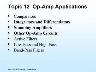
Topic 12 Op-Amp Applications
- Comparators
- Integrators and Differentiators
- Summing Amplifiers
- Other Op-Amp Circuits
- Active Filters
- Low-Pass and High-Pass
- Band-Pass Filters
2
Op-Amp Integrator
- The op-amp provides a constant-current source for
the capacitor, causing it to charge at a linear
rate.
3
Reduced Gain Op-Amp Integrator
- A feedback resistor limits the gain at low
frequency since the reactance of Cf increases,
causing an increase in voltage gain. - Any output offset voltage can also be reduced.
Rf is normally gt 10 Rin
4
12.2.2 Differentiator
- Differentiator A circuit whose output is
proportional to the rate of change of its input
signal.
5
Reduced Gain Op-Amp Differentiator
- The added Rin resistor limits the gain at high
frequency since the reactance of Cf is extremely
low at higher frequencies
6
12.3 Summing Amplifiers
- Summing amplifier An op-amp circuit that
produces an output proportional to the sum of its
input voltages.
7
Summing Amplifiers Example (1)
- Example 16.4 Determine the output voltage.
Solution
Voltage gain equals -1 for all the inputs.
(-1)(3V 6V 4V) -13V
8
Summing Amplifiers Example (2)
- Example 16.5 Determine the output voltage.
Solution
Voltage gain equals -0.1 for all the inputs.
(-0.1)(10V8V7V) -2.5V
9
General Summing Circuits
- General-class equation An equation derived for
a summing amplifier that is used to predict the
circuit output for any combination of input
voltages. - Determine the Rf / R ratio for each branch.
- Represent each branch as the product of its
resistance ratio and input voltage. - Write the equation as the sum of these products.
10
Summing Amplifiers Example (3)
- Example 16.6 Determine the output voltage for
the 3 sets of inputs.
V1(V) V2(V) V3(V)
10 0 10
0 10 10
10 10 10
Solution
11
Simplified D/A Converter
- One summing amplifier application is as a
digital-to-analog (D/A) converter. - Digital-to-analog (D/A) converter A circuit
that converts digital circuit outputs to
equivalent analog voltages.
12
Averaging Amplifier
- By using the proper input and feedback resistors,
a summing amplifier can be an averaging
amplifier. - Averaging amplifier A summing amplifier that
provides an output proportional to the average of
the input voltages.
13
Difference Amplifier (Subtractor)
- Difference amplifier A summing amplifier that
provides an output proportional to the difference
between two input voltages. Also called a
subtractor.
In order to work properly, a difference amplifier
must have values of R1 R2 and R3 R4
14
12.4 Other Op-Amp Circuits
- Instrumentation amplifier A high-gain and
high-CMRR circuit used to amplify low-level
signals in process control and measurement
applications.
15
Audio Amplifier
- Audio amplifier The final audio stage in
low-power communications receivers, used to drive
the speakers.
16
Voltage-Controlled Current Source
- Voltage-controlled current source A circuit
with a constant-current output controlled by the
circuit input voltage.
17
Precision Rectifier
- Precision rectifier A clipper that consists of
a diode and an op-amp. The circuit can clip
extremely low-
level input signals.
18
Op-Amp Applications (1)
- A comparator is a circuit used to compare two
voltages. - Most comparators use a voltage-divider to set the
reference voltage. - An op-amp integrator provides a linear/ramp
output waveform with a square-wave input. - A differentiator is a circuit whose output is
proportional to the rate of change of its input
signal. - A summing amplifier produces an output
proportional to the sum of its input voltages. - A averaging amplifier provides an output
proportional to the average of the input
voltages. - A difference amplifier (subtractor) provides an
output proportional to the difference between two
input voltages. - Chapter 16 Problems (min.) 1, 3, 5, 7, 11, 13,
15, 17, 19
Recommended
CrystalGraphics Presentations


