
Stormwater Runoff Analysis of Gallup Road Subdivision site Before and After Construction and Retenti - PowerPoint PPT Presentation
1 / 1
Title:
Stormwater Runoff Analysis of Gallup Road Subdivision site Before and After Construction and Retenti
Description:
There are several different practices that could be chosen on order to meet the ... case of constant head, so the drainage time will actually be somewhat higher. ... – PowerPoint PPT presentation
Number of Views:51
Avg rating:3.0/5.0
Title: Stormwater Runoff Analysis of Gallup Road Subdivision site Before and After Construction and Retenti
1
Stormwater Runoff Analysis of Gallup Road
Subdivision site Before and After Construction
and Retention Practice Design
- John Domm, Dr Theodore Endreny. ERE-540
Engineering Hydraulics and Hydrology 310-B Bray
Hall, SUNY College of Environmental Science and
Forestry, Syracuse, NY 13210
- Location Characteristics
- The Gallup Road Subdivision is a proposed
development of a 40 acre farm field into a
residential housing subdivision. The proposal
includes 1 acre lots with the roads required to
access the lots on the interior of the site.
There is concern that the increased impervious
area and altered land use will cause flooding of
areas directly adjacent to the northern border of
the site. The field is currently a used to
produce hay to feed livestock. For analysis it
will be considered a meadow in good condition - Design Goals
- Analyze current runoff situation for a 5 and 10
year return period 24 hour storm - Determine the increase in runoff due to the
development of the site - Design a practice to contain and slowly release
all post-development runoff from a 10 year storm - Design Constraints
- Stormwater Practice must fit within a 2 acre
parcel - Practice must be aesthetically pleasing for a
residential neighborhood - Practice must be located at the lowest elevation
area of the site - Any surface water drainage must discharge into
existing channels. - Surface Drainage for 10 year storm must not
exceed 28 cfs (undeveloped discharge)
Design Findings The solution I have chosen is a
wet retention pond which will have a surface area
of approximately ¾ acre. The depth will vary up
to 6 feet in the center of the pond. Around the
perimeter of the pond there is a buffer area for
infiltration which slopes up 8 feet to ground
level in 2 stages. This buffer area will consist
of porous soil which will allow water to
infiltrate to a subsurface drain at the depth of
15 feet. This drain will connect to wells
drilled to the depth of the water table to allow
stormwater from the pond to recharge the
groundwater once it has filtered through the
porous soil. In addition, there will be a
surface outlet from the drain which will allow
excess water unable to enter the water table to
drain into surface channels. The surface area of
the stormwater portion of the pond will be 1-1/2
acres. There will be an overflow on the north
side of the pond at a level of 5 feet above the
permanent portion of the pond. This will allow a
storage capacity of approximately 7.5 acre-feet
of water, which is nearly double the projected
runoff from the 10 year storm, allowing a factor
of safety. The overflow will connect to a
natural channel on the north side of the
property. The stormwater inlet will be in the
south side of the practice, discharging into the
infiltration portion of the pond, and flowing
into the wet portion via a rip-rap channel.
The calculated required permeability of the
infiltration soil needed in order to meet the
maximum acceptable discharge of 28cfs for a full
pond is a K of 415 gal/day/ft2. Using a safety
factor of 2, this comes out to a K of 208
gal/day/ft2. The chosen K value will give a
drainage time of 4.7 hours to empty the
stormwater portion of the pond, assuming constant
head. This is not a case of constant head, so
the drainage time will actually be somewhat
higher.
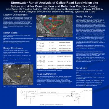
Pond Location
Figure 2. Aerial Photograph of site with
proposed lot lines and roadways
Calculation of Pre-Development Runoff Conditions
- Conclusion
- This solution meets all criteria required for
success of the project - The maximum discharge from the site will be 14cfs
for a 10 year storm. - The stormwater retention pond is 1.5 acres in
area- less than the required 2 acres. - The pond is able to be located at the lowest
point of the site - Surface drainage is able to exit into an existing
channel - The pond will provide wildlife habitat and
recreational opportunities for the neighborhood
residents
Calculation of Post-Development Runoff Conditions
Design Alternatives There are several different
practices that could be chosen on order to meet
the design constraints. These include wet pond,
or extended detention wetland. If the drainage
area was broken up into a series of smaller
drainage areas, other practices could be
employed, such as the shallow infiltration basin,
or a bioretention area. For this site I have
chosen to design a wet retention pond which also
incorporates an infiltration area around the
perimeter.
Figure 1. Aerial Photograph of site with soil
contours
Figure 3. Typical cross section of retention pond
Recommended
CrystalGraphics Presentations


