
Timer Mode 0 - PowerPoint PPT Presentation
1 / 27
Title:
Timer Mode 0
Description:
Mode 0 is exactly like mode 1 except that it is a 13-bit timer ... Some 8051 assemblers provide this way. -200 = -C8H 2's complement of 200 = 100H C8H = 38 H ... – PowerPoint PPT presentation
Number of Views:88
Avg rating:3.0/5.0
Title: Timer Mode 0
1
Timer Mode 0
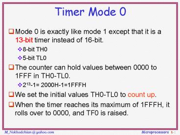
- Mode 0 is exactly like mode 1 except that it is a
13-bit timer instead of 16-bit. - 8-bit TH0
- 5-bit TL0
- The counter can hold values between 0000 to 1FFF
in TH0-TL0. - 213-1 2000H-11FFFH
- We set the initial values TH0-TL0 to count up.
- When the timer reaches its maximum of 1FFFH, it
rolls over to 0000, and TF0 is raised.
2
Timer Mode 2
- 8-bit timer.
- It allows only values of 00 to FFH to be loaded
into TH0. - Auto-reloading
- TL0 is incremented continuously when TR01.
- next example 200 MCs delay on timer 0.
- See Examples 9-14 to 9-16
3
Steps of Mode 2 (1/2)
- Chose mode 2 timer 0
- MOV TMOD,02H
- Set the original value to TH0.
- MOV TH0,38H
- Clear the flag to TF00.
- CLR TF0
- After TH0 is loaded with the 8-bit value, the
8051 gives a copy of it to TL0. - TL0TH038H
- Start the timer.
- SETB TR0
4
Steps of Mode 2 (2/2)
- The 8051 starts to count up by incrementing the
TL0. - TL0 38H, 39H, 3AH,....
- When TL0 rolls over from FFH to 00, the 8051 set
TF01. Also, TL0 is reloaded automatically with
the value kept by the TH0. - TL0 FEH, FFH, 00H (Now TF01)
- The 8051 auto reload TL0TH038H.
- Clr TF0
- Go to Step 6 (i.e., TL0 is incrementing
continuously). - Note that we must clear TF0 when TL0 rolls over.
Thus, we can monitor TF0 in next process. - Clear TR0 to stop the process.
- Clr TR0
5
Timer 1 Mode 2 with internal Input
XTAL oscillator
12
C/T 0
overflow flag
TL1
TF1
reload
TR1
TH1
TF goes high when FF 0
6
Example 9-15
- Find the frequency of a square wave generated on
pin P1.0. - Solution
- MOV TMOD,2H Timer 0,mode 2
- MOV TH0,0
- AGAINMOV R5,250 count 250 times
- ACALL DELAY
- CPL P1.0
- SJMP AGAIN
- DELAYSETB TR0 start
- BACK JNB TF0,BACK wait until TL0 ovrflw
auto-reload - CLR TR0 stop
- CLR TF0 clear TF
- DJNZ R5,DELAY
- RET
- T 2 (250 256 1.085 ?s) 138.88 ms, and
frequency 72 Hz.
7
Example 9-16
- Assuming that we are programming the timers for
mode 2, find the - value (in hex) loaded into TH for each of the
following cases. - (a) MOV TH1,-200 (b) MOV TH0,-60 (c) MOV
TH1,-3 - (d) MOV TH1,-12 (e) MOV TH0,-48
- Solution
- Some 8051 assemblers provide this way.
- -200 -C8H ? 2s complement of 200 100H C8H
38 H
8
Example 9-17 (1/2)
- Find
- (a) the frequency of the square wave generated in
the following code - (b) the duty cycle of this wave.
- Solution
- MOV TH0,-150 uses 150 clocks.
- The DELAY subroutine 150 1.085 ?s 162 ?s.
- The high portion is twice tat of the low portion
(66 duty cycle). - The total period high portion low portion
- T 325.5 ?s 162.25 ?s 488.25 ?s
- Frequency 2.048 kHz.
9
Example 9-17 (2/2)
- MOV TMOD,2H Timer 0,mode 2
- MOV TH0,-150 Count150
- AGAINSETB P1.3
- ACALL DELAY
- ACALL DELAY
- CLR P1.3
- ACALL DEALY
- SJMP AGAIN
- DELAYSETB TR0 start
- BACK JNB TF0,BACK
- CLR TR0 stop
- CLR TF0 clear TF
- RET
high period
low period
10
Counter
- These timers can also be used as counters
counting events happening outside the 8051. - When the timer is used as a counter, it is a
pulse outside of the 8051 that increments the TH,
TL. - When C/T1, the counter counts up as pulses are
fed from - T0 timer 0 input (Pin 14, P3.4)
- T1 timer 1 input (Pin 15, P3.5)
11
Port 3 Pins Used For Timers 0 and 1
12
Timer/Counter selection
13
Counter Mode 1
- 16-bit counter (TH0 and TL0)
- TH0-TL0 is incremented when TR0 is set to 1 and
an external pulse (in T0) occurs. - When the counter (TH0-TL0) reaches its maximum of
FFFFH, it rolls over to 0000, and TF0 is raised. - Programmers should monitor TF0 continuously and
stop the counter 0. - Programmers can set the initial value of TH0-TL0
and let TF01 as an indicator to show a special
condition. (ex 100 people have come).
14
Timer 0 with External Input (Mode 1)
15
Counter Mode 2
- 8-bit counter.
- It allows only values of 00 to FFH to be loaded
into TH0. - Auto-reloading
- TL0 is incremented if TR01 and external pulse
occurs. - See Figure 9.6, 9.7 for logic view
- See Examples 9-18, 9-19
16
Example 9-18 (1/2)
- Assuming that clock pulses are fed into pin T1,
write a program for - counter 1 in mode 2 to count the pulses and
display the state of the - TL 1 count on P2.
- Solution
- MOV TMOD,01100000B mode 2, counter 1
- MOV TH1,0
- SETB P3.5 make T1 input port
- AGAINSETB TR1 start
- BACK MOV A,TL1
- MOV P2,A display in P2
- JNB TF1,Back overflow
- CLR TR1 stop
- CLR TF1 make TF0
- SJMP AGAIN keep doing it
17
Example 9-18 (2/2)
- Timer 1 as an event counter fed into pin3.5.
- SETB P3.5 make P3.5 an input port by making it
high
P2 is connected to 8 LEDs and input T1 to pulse.
18
Example 9-19 (1/3)
- Assume that a 1-Hz frequency pulse is connected
to input pin 3.4. - Write a program to display counter 0 on an LCD.
Set the initial - value of TH0 to -60.
- Solution
- Note that on the first round, it starts from 0
and counts 256 events, since on RESET, TL00. To
solve this problem, load TH0 with -60 at the
beginning of the program.
19
Example 9-19 (2/3)
- ACALL LCD_SET_UP initialize the LCD
- MOV TMOD,00000110B Counter 0,mode2
- MOV TH0,-60
- SETB P3.4 make T0 as input
- AGAINSETB TR0 starts the counter
- BACK MOV A,TL0 every 60 events
- ACALL CONV convert in R2,R3,R4
- ACALL DISPLY display on LCD
- JNB TF0,BACK loop if TF00
- CLR TR0 stop
- CLR TF0
- SJMP AGAIN
20
Example 9-19 (3/3)
- converting 8-bit binary to ASCII
- CONV MOV B,10 divide by 10
- DIV AB
- MOV R2,B save low digit
- MOV B,10 divide by 10 once more
- DIV AB
- ORL A,30H make it ASCII
- MOV R4,A
- MOV A,B
- ORL A,30H
- MOV R3,A
- MOV A,R2
- ORL A,30H
- MOV R2,A ACALL LCD_DISPLAY here
- RET
R4
R3
R2
21
A Digital Clock
- Example 9-19 shows a simple digital clock.
- If we feed an external square wave of 60 Hz
frequency into the timer/counter, we can generate
the second, the minute, and the hour out of this
input frequency and display the result on an LCD. - You might think that the use of the instruction
JNB TF0,target to monitor the raising of the
TF0 flag is a waste of the microcontrollers
time. - The solution is the use of interrupt. See Chapter
11. - In using interrupts we can do other things with
the 8051. - When the TF flag is raised it will inform us.
22
GATE1 in TMOD
- All discuss so far has assumed that GATE0.
- The timer is stared with instructions SETB TR0
and SETB TR1 for timers 0 and 1, respectively. - If GATE1, we can use hardware to control the
start and stop of the timers. - INT0 (P3.2, pin 12) starts and stops timer 0
- INT1 (P3.3, pin 13) starts and stops timer 1
- This allows us to start or stop the timer
externally at any time via a simple switch.
23
GATE (external control)
- Timer 0 must be turned on by SETB TR0
- If GATE1 count up if
- INT0 input is high
- TR01
- If GATE0 count up if
- TR01
24
(No Transcript)
25
(No Transcript)
26
(No Transcript)
27
(No Transcript)
Recommended
CrystalGraphics Presentations


