Operating Limits During TPL Deuterium Load _______________________ - PowerPoint PPT Presentation
1 / 37
Title:
Operating Limits During TPL Deuterium Load _______________________
Description:
Dismantle one sector (20 ) of the Toroidal Pumped Limiter ... 5.4 g if only CFC concerned (55 % of total) total. presently. found. with D-losses. with time ... – PowerPoint PPT presentation
Number of Views:20
Avg rating:3.0/5.0
Title: Operating Limits During TPL Deuterium Load _______________________
1
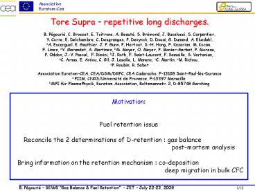
Tore Supra repetitive long discharges. B.
Pégourié, C. Brosset, E. Tsitrone, A. Beauté, S.
Brémond, J. Bucalossi, S. Carpentier, Y. Corre,
E. Delchambre, C. Desgranges, P. Devynck, D.
Douai, G. Dunand, A. Ekedahl, aA. Escarguel, E.
Gauthier, J. P. Gunn, P. Hertout, S.-H. Hong, F.
Kazarian, M. Kocan, F. Linez, aY. Marandet, A.
Martinez, bM. Mayer, O. Meyer, P. Monier-Garbet,
P. Moreau, P. Oddon, J.-Y. Pascal, F. Rimini,
bJ. Roth, F. Saint-Laurent, F. Samaille, S.
Vartanian, aC. Arnas, E. Aréou, C. Gil, J.
Lasalle, L. Manenc, aC. Martin, aM. Richou, aP.
Roubin, R. Sabot Association Euratom-CEA,
CEA/DSM/DRFC, CEA Cadarache, F-13108
Saint-Paul-lès-Durance a PIIM, CNRS/Université de
Provence, F-13397 Marseille bMPI für
PlasmaPhysik, Euratom Association, Boltzmannstr.
2, D-85748 Garching
Motivation Fuel retention issue
Reconcile the 2 determinations of D-retention
gas balance
post-mortem
analysis Bring information on the retention
mechanism co-deposition
deep migration
in bulk CFC
2
A dedicated experiment Deuterium Inventory in
Tore Supra
3
(No Transcript)
4
Time schedule of the campaign
10 days of operation in 3 weeks 160 identical
long discharges (between 1 and 2 minutes) 5h of
plasma (about a normal year of operation)
Carbonization 13C boronization
100 10-1 10-2 10-3 10-4 10-5
Pressure in the torus (Pa)
0 50 100 150 200
250 300 350 400
Time (h) since the beginning of the campaign
5
Disruptions due to UFOs limit plasma duration
6
85 of disruptions associated to flake ejection
No change in core edge parameters (moderate
increase in impurity content)
7
Deposit pattern evolves during experiment
Thick deposits private flux regions No plasma ,
but radiation CX atoms Competition growth /
erosion Pattern characteristic to each scenario
Deposits are thermally poorly attached to
CFC Increase of deposit thickness seen as
increase of surface temperature
Beginning
End of 1st phase
T-Tref
T-Tref
8
(No Transcript)
9
(No Transcript)
10
Global wall inventory (1)
During plasma operation, C is ? 0.01 D in the
pumped gas H/D decreases from 20 to 2
during the campaign
Total correction 0.4g D
11
(No Transcript)
12
(No Transcript)
13
(No Transcript)
14
Tile analysis NRA average D/C profiles
Erosion zone 200C
Thin deposits 120C
Thick deposits 500-600C (up to 1000C close to
the tangency point)
Gaps lt 400C
Poloidal gaps
Top of the tiles
15
Tile analysis Thermodesorption
2g/m2
0.4g/m2
16
Integrated D-inventory
NRA (top lateral faces)
TDS (top) NRA (lateral)
17
D-inventory effect of time
Decrease of the D-content between end of
operation and analysis
Estimated TPL D-inventory at the end of plasma
operation 7.2 g if CFC and deposits concerned
(70 of total) 5.4 g if only CFC concerned
(55 of total)
18
Summary
19
Additional viewgraphs
20
Previous TS results (C. Brosset et al., JNM 2005)
All deposits far from LCFS but significant plasma
flux (? to B) Deposits on TPL surface, close to
LCFS but no direct plasma flux not
collected Collection after campaign with high
power discharges (high temperature of deposits)
0.3g D found (2.6g estimated Wall
Inventory) Extrapolated to present Wall
Inventory (10g) ? 1.2g
21
Attempt for global C-balance (from J.Hogan et
al., IAEA 2006)
Net redeposition cleaning of whole vacuum
chamber 800g deposits scrapped from PFCs
Net erosion net redeposition (neglects erosion
due to glows)
agrees with erosion from confocal mscopy 1000g
eroded from TPL surface
Only 55-65 of local C-redeposition
UFO 0.2mg C (3mm3mm3mm) 500 UFOs during
D-loading experiment 0.12g C (510-4 of gross
erosion)
22
Extrapolation fuel retention to ITER
From D-loading experiment 5h of plasmas ? 10g of
increase of wall D-inventory ? 4g D found in
TPL 1.3g in erosion zones
2.7g in deposits TPL main source of C ?
other PFCs likely deposited areas ? 8.7g in
deposits
Extrapolation to ITER speculative because Not
the same geometry Not the same edge
parameters Not the same surface temperatures
With respect to flux on PFCs (2 orders of
magnitude) 150g/h ? 700g T after 40 nominal
discharges (400s)
In erosion zones, with respect to integrated
flux (2 orders of magnitude) 20g/h with
respect to loaded surface (1order of magnitude)
2g/h In deposited zones, with respect to net
erosion (Redep 0.55 in TS 46g/h eroded C)
(Redep 0.99 in ITER
27g/h) 1.5g/h (22-4)g/h ? 700g T after 300-1600
nominal discharges (400s)
23
(No Transcript)
24
(No Transcript)
25
(No Transcript)
26
MARFE causes PLH switched off by security
PLH switced off if radiation increases above
fixed limit Line of sight of the security system
located in midplane With increasing impurity
content, MARFEs are triggered by smaller
perturbations
27
Hot spot outgassing (impurity) MARFE
flake ejection Prad increases
swith-off PLH by security density limit
28
Deposit pattern evolves during experiment
Deposits are thermally poorly attached to
CFC Increase of deposit thickness seen as
increase of surface temperature
Thick deposits private flux regions on TPL No
plasma , but radiation CX atoms Competition
growth / erosion Deposit pattern characteristic
to each scenario
Movie of the DTTPL during the 1st phase of the
experiment
29
Plasma-wall interaction Carbon erosion
CII emission on net erosion zones gaps CD on
net erosion zones leading edge
Gross erosion estimated from Ytot BBQ
simulations (J.Hogan et al., IAEA 2006) For the
whole campaign 230 g
CD 431nm
30
Constant plasma edge parameters
31
Constant plasma core parameters
32
Moderate increase of impurity content
Constant core and edge plasma parameters
ne(0)2.71019m-3 Te(0)3.5keV
ne(a)21018m-3 Te(a)25eV Moderate increase
of impurity content
33
Sample analysis
34
(No Transcript)
35
Poloidal gaps, thin deposits
Bottom (copper)
Top (plasma)
36
Poloidal gaps, thick deposits
Bottom (copper)
Top (plasma)
37
Erosion zones Mechanism for D-retention
Erosion zone D-content 100 that expected from
implantation


