
Possible%20ASIC%20Options%20within%20a%20Common%20Readout%20Infrastructure - PowerPoint PPT Presentation
Title:
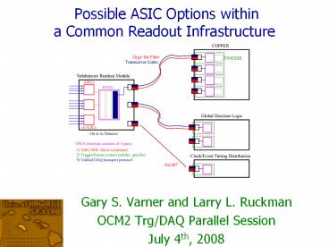
Possible%20ASIC%20Options%20within%20a%20Common%20Readout%20Infrastructure
Description:
Separate discussions with subdetector groups (if interested) Precision Timing ... 4k samples (8x rows interleave) Multi-hit buffering. Fast-scan readout mode ... – PowerPoint PPT presentation
Number of Views:549
Avg rating:3.0/5.0
Title: Possible%20ASIC%20Options%20within%20a%20Common%20Readout%20Infrastructure
1
Possible ASIC Options within a Common Readout
Infrastructure
- Gary S. Varner and Larry L. Ruckman
- OCM2 Trg/DAQ Parallel Session
- July 4th, 2008
2
Todays Topics
- There are two separate issues
- Common trigger/clock/data link
- Possible common/related readout
ASICs/firmware/software - Many subdetector-specific details
- Just highlight some issues
- Separate discussions with subdetector groups (if
interested) - Precision Timing
- Better clock distribution follow ps timing
development - Better T0 determination
- System approach
- Defer specifics of implementation
- Suggest a common approach
3
A Common Approach for Belle
Fastbus
Amp
Shaper
Discr./
trigger
Q-T ASIC
MTDC ASIC
CDC, ACC, KLM, ECL, TOF
Not SVD
Upgrades
Fastbus ? COPPER MTD132A ? AMT3
4
Proposed Common Approach for Belle
Part b
Part a
5
Key Enabling Technology
oscilloscope on a chip
LABRADOR Commercial
Sampling speed 1-3.7 GSa/s 2 GSa/s
Bits/ENOBs 12/9-10 8/7.4
Power/Chan. lt 0.05W 5-10W
Cost/Ch. lt 10 (vol) gt 1k
- 2 GSa/s, 1GHz ABW Tektronics Scope
- 2.56 GSa/s LAB
- PoS PD07 026, 2006
- NIM A583 447-460, 2007
- NIM A591 534-545, 2008
- arXiv 0805.2225 (submitted NIM A)
6
Other Enabling Technologies
- FPGA as
- Discriminator
- ADC
- TDC
- Event FIFO
- Feature extract
- SerDes fiber
- Journal Instr. 1 P07001, 2006
- Journal Instr. 2 P04006, 2007
- PRO timing encoding, in preparation
7
Test System Readout Block Diagram
Giga-bit Fiber
Photo- Sensor
MCP MAIN
BLAB2
cPCI Crate (Linux)
BLAB2
x7
cPCI CARD
BLAB2
BLAB2
COPPER
- Up to 7x64 channels per cPCI card
- Up to 32,256 channels/cPCI crate
Very cost effective, board hardware already exists
8
Possible ASIC Options
9
Starting Place BLAB2 PD scale readout
- Initial Target New TOP/iTOP/f-DIRC Readout System
6
1024
Gen. 0 Prototype (LAB3)
Submitted for fabrication June, 2008 (avail
autumn)
10
Design Basis Buffered LABRADOR (BLAB1) ASIC
- Single channel
- 64k samples deep, same SCA technique as
LAB, no ripple pointer - Multi-MSa/s to Multi-GSa/s
- 12-64us to form Global trigger
Arranged as 128 x 512 samples Simultaneous
Write/Read
3mm x 2.8mm, TSMC 0.25um
11
BLAB1 Architecture
200ps/sample
FPGA-based TDC 10-bits in 1us (300ps resolution)
12
BLAB1 Sampling Speed
Can store 13us at 5GSa/s (before wrapping around)
Single sample 200/SQRT(12) 58ps In practice,
have often been using 512 samples
200ps/sample
13
Buffered LABRADOR (BLAB1) ASIC
- 10 real bits of dynamic range, single-shot
1.6V dynamic range
Measured Noise
1 mV
14
Typical single p.e. signal Burle
100
Overshoot/ringing
50
0
-50
-100
voltage (mV)
-150
Using RF Amplifier System (43dB gain)
-200
-250
-300
-350
0
10
20
30
40
50
60
70
80
90
time (ns)
15
Excellent Timing Performance
- Two separate BLAB1 ASIC with a common sampling
strobe - RF split the Agilent pulse with additional cable
delay in the 2nd channel
Example of tailoring to need
CH1
6.4 psRMS
CH2
16
Typical System Specifications
FPGA
4x TARGET
- Readout link
- Initially USB2 gt50kHz Event sustained
(20Mbit/s)? - Fiber links to make TARGET RO limited and use to
collect trigger information
FINESSE
17
Need to specify ASIC requirements
- E.g. What gain needed?
- At 106 gain, each p.e. 160 fC
- In typical 5ns pulse, Vpeak dQ/dt R 32uA
R 32mV R kW - AC Coupling mode
18
Signal Amplitude
- DC Coupling mode (reduced dynamic Range)
19
Design Reference TARGET ASIC
- 3 x 3 mm die
- 4k samples (8x rows interleave)
- Multi-hit buffering
- Fast-scan readout mode
- Belle TOF counter PMT pulse
- 16 channel waveform recording
- Trigger prototype
20
Evaluation Board TARGET ASIC
21
Trigger Logic
- Analog (Sum of Ch. ON) Digital OR output
- 1-Shot or Raw comparator output
22
Trigger Performance
- Good Adjustment Range
- Reasonable current values
- Stable, good coincidence capability
23
Specific Issues
- Pixel how to event match (track matching)
- SVD APV25-type OK, but faster pipe drain
desired - CDC matched amp/LVDS outputs
- KLM 2-level FPGA readout OK? (FPGA-based TDC
good enough) - PID with Precision Timing precision clock
distribution
24
Clock Distribution System
25
CDCE62005 Pico BTS/Data Com Clock35 Frequency
Synthesizer/Jitter Cleaner
Features
Benefits
- Input frequencies from 3MHz to 500MHz
- Crystal Inputs from 2MHz to 42MHz
- Output frequencies from 4.25MHz to 1.175GHz
- Output up to 5 LVPECL/5 LVDS/10 LVCMOS
- Individual phase adjust
- Optional high swing LVPECL mode
- Wide-range integer divide selectable by output
- Low output skew ( 20ps, typ)
- Integrated/External PLL Loop Filter
- Low jitter (lt 1ps RMS)
- On-chip EEPROM
- Fully Integrated twin VCOs support wide output
frequency range - Wide input/output frequency range supports high
and low end of frequency standards - Selectable input/output standards reduces
translation logic - Integrated/external loop filter provides
flexibility - EEPROM saves default start-up settings
- SPI interface provides in-system programming
- QFN-48 package, Tem -40 to 85 C
Applications
John Anderson HEP Electronics Group Argonne
National Laboratory Presented by Gary Drake
- Wireless BTS
- (Pico, WiMax cells, Macro Base band)
- Data Communications
- Medical
- Test Equipment
- Jitter Cleaners
In Design
May/08
In Production
Oct/07
Sampling
26
Testbed FNAL T-979
27
Summary
- New technologies options
- Low cost, high performance recording
- Internal gain/triggering (min. external noise)
- Fiber-optic communications (back to future)
- Many details
- Work with subdetector groups (offer, not forced)
- Biggest issues amplification and form factors
- Variants
- While different in details, basics of buffer and
trigger management common - Common protocols for subdetector readout
developers to design to (common resources)
28
Back-up slides
29
Readout System Block Diagram
Giga-bit Fiber
CAMAC For beam-test only!
Photo- Sensor
MCP MAIN
BLAB2
cPCI Crate (Linux)
BLAB2
x7
cPCI CARD
BLAB2
x1
BLAB2
CAMAC CARD
CAMAC Backplane
- Up to 7x64 channels per cPCI card
- CAMAC card for SLAC beam test
- Up to 32,256 channels/cPCI crate
Very cost effective, board hardware already exists
30
(symmetry partner in hit plane)
Comparison of UH timing slot 7, pad 15 to
Philips slot 16 for run 27, pos 1, direct
photons
slot 1, pad 28
s240ps
SLAC custom CFD Philips ADC/TDC
(close neighbor in hit plane)
slot 7, pad 30
slot 6, pad 61
s170ps
s275ps
Jochen Schwiening analysis (preliminary)
delta(time) (ns)
31
Gain Needed
Amplifiers dominate board space
Readout ASIC tiny (14x14mm for 16 channels)
- What gain needed?
- At 106 gain, each p.e. 160 fC
- At 2x10⁵ gain (better for aging), each p.e. 32
fC - In typical 5ns pulse, Vpeak dQ/dt R 32uA
R 32mV R kW (6.4mV)
32
Real MCP-PMT Signals (with BLAB2)
Residual Time Walk
7-8 psRMS
Rather robust for amplitude invariant
signals,TOF still hard, but can shape extract
33
BLAB2 Density and Cost
- 16 input channels
- For large-scale systems, cost very competetive
BLAB ASIC cost estimate
Based on actual fabrications or quotations from
foundaries
34
Storage Mode
512ns
Row 1
Row 2
Row 3
Row 4
Row 5
Row 6
Row 7
Row 8
- Storage configuration (4k samples 4us)
- 16 channels, each of 8 rows of 512 samples
- Overlapped, continuous sampling (window select)
- Readout select 16ns tick and read with nearest
16ns - Multi-hit buffering (only block 1 row), continue
sampling ? 10 deadtime ? 1 deadtime (30kHz,
30us)
Recommended
CrystalGraphics Presentations


