
NASA Human Integration Design Handbook HIDH - PowerPoint PPT Presentation
1 / 1
Title: NASA Human Integration Design Handbook HIDH
1
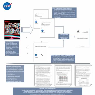
NASA Human Integration Design Handbook (HIDH)
Revitalization of Space-Related Human Factors,
Environmental, and Habitability Data and Design
Guidance
- Space Flight Human System Standard
- Updates crew health and performance standards to
apply to all future systems with human crews
(spacecraft, landers, habitats, rovers, EVA
suits, etc.) - Requires that program specific requirements be
derived from the standard with guidance from the
HIDH
STANDARDS
EXAMPLE The vehicle / habitat atmosphere
including pressure, humidity, temperature . . .
shall be controlled in a manner that yields a
healthy comfortable environment of respirable air
to the crew
PROGRAM-SPECIFIC REQUIREMENTS
These documents drive program -specific
requirements
Pitch
Yaw
- NASA-STD-3000
- Served as NASAs first human factors standard
- Specified how to design systems to support human
health, safety, and productivity during space
flight - Was written primarily for the International
Space Station
- EXAMPLE
- Data on temperature effects on human physiology
and performance - Guidance for limits and implementation based on
expertise, lessons learned
EXAMPLE The system shall maintain the
atmospheric temperature within the range of 18 ºC
(64.4 ºF) to 27 ºC (80.6 ºF) during all nominal
flight operations, excluding suited operations,
ascent, entry, landing, and post landing.
HANDBOOK
- Human Integration Design Handbook (HIDH)
- Provides guidance and data to aid vehicle /
habitat designers in human-system integration - Aids requirements writers in development of
human-system integration requirements from SFHSS
Standards
- Handbook Chapters include
- Anthropometry And Biomechanics
- Human Performance Capabilities
- Natural And Induced Environments
- Architecture
- User Interfaces
- Hardware And Equipment
- Facility Management
- Health Management
- Extra-Vehicular Activity (EVA)
5.2.2.2 Growth Trend Past experience indicates
historical changes in anthropometric
dimensions such as height, weight, and other
measurements. These changes that occur from
generation to generation are referred to as
secular change and the impact of such changes can
be significant for hardware design. In order
to predict secular change, the first step is to
estimate the stature of a future population based
on trends. Next, a representative population or
baseline database is selected. Body dimensions
are then defined against the stature for each
subject. Finally, the estimated future stature is
used to calculate estimated future segment
lengths and other dimensions based on the
relationships between these dimensions
and subject stature. This procedure is followed
through the following steps 1. Select a
population similar to the desired population that
includes stature over several decades. Plot the
average stature and determine a trend. Project
the mean stature to the desired future date. One
source of growth trend data is published by the
Center for Disease Control from their National
Health and Nutrition Examination Surveys
that they conduct approximately every 10 years.
Figure 5.2-1 shows stature growth data for the
American male. As can be seen, growth seems to
be leveling off at 69.5 inches and a reasonable
estimate of stature in 2015 would be 69.5 inches.
The male astronaut population data (adapted
from Air Force surveys) estimates the mean
stature at 70.3 inches in 2015. This was the
estimate used to create the data in the example
tables in paragraph 5.2.1.
- 5.5.4.3 Countermeasures for Rotational
Acceleration - Rotational accelerations should not exceed 2
rad/s2. Rotational velocities in pitch and roll
should not exceed the limits specified in Figure
5.3.3.2-1. These rotational limits apply for
centers of rotation at the heart or outside the
heart. However, for rotations outside the heart,
the linear accelerations induced at the heart (by
rotational accelerations and velocities) must be
included in the linear accelerations, which are
evaluated against the limits described in Section
5.3.3.1. - The data in this figure apply when crewmembers
are appropriately trained and restrained and
utilize G protection (Refer to paragraph 5.3.4).
The figure presents three limiting conditions. - The solid red line corresponds to maximum
allowable rotation rates for - automated crew abort/escape.
- The dashed blue line indicates the design limit
for conditioned - crewmembers during nominal ascent and entry.
- The dotted green line shows the design limit
for long-duration, - deconditioned, and/or ill and/or injured
crewmembers.
Figure 5.5-1 Angular Rate Limit
Tolerance to rotational motion must be considered
in terms of both rotational acceleration and
rotational velocity. For vehicle occupants, the
translational and angular motion must be assessed
at each occupants location in the vehicle.
Also, the effects of the angular component of
occupant motion will vary with superimposed
linear acceleration.
Figure 5.2-1 - Mean Male Stature Example
WE INVITE YOUR PARTICIPATION ! NASA-JSC HIDH
development team has finalized the format and
began developing section with subject matter
experts. Handbook expansion and maintenance is
planned to assure its retention as a resource for
human spaceflight. If you are interested in
participating in the writing, reviewing,
enhancing of this document, contact any of the
below Ken Stroud 281.483.5098, Lynn Pickett
281.483.6689, Barry Tillman 281.483.7131