
2' Electrical Ladder Logic Diagrams - PowerPoint PPT Presentation
1 / 13
Title:
2' Electrical Ladder Logic Diagrams
Description:
So this ELLD is a physical representation of the Boolean logic equation. L=S. 3 ... The Boolean logic equations for the rungs in the ladder diagram are ... – PowerPoint PPT presentation
Number of Views:761
Avg rating:3.0/5.0
Title: 2' Electrical Ladder Logic Diagrams
1
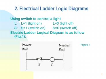
2. Electrical Ladder Logic Diagrams
- Using switch to control a light
- L L1 (light on) L0 (light off)
- S S1 (switch on) S0 (switch off)
- Electric Ladder Logical Diagram is as follow
(Fig.1)
Figure 1
2
2. Electrical Ladder Logic Diagrams (ELLD)
- The structure of ELLD is
- - left rail with power -gt power rail
- - right rail with neutral -gt neutral rail
- - one path called rung
- It is clear with the notation on Fig.1, when L1
-gt S1 and when L0 -gt S0 - So this ELLD is a physical representation of the
Boolean logic equation - LS
3
2. Electrical Ladder Logic Diagrams
- Fig.2 shows a multiple rungs (two rungs).
- The problem
- - Two lights, L1 and L2.
- - Three switches, S1, S2, S3
Fig.2 physically represents L1S1S2 (Rung
1) L2S2S3 (Rung 2)
4
2. Electrical Ladder Logic Diagrams
Control Relays Instead of using one switch to
control one light or object, a generic commonet
of hardwired control implementation is a control
relay, see Fig.3. Features of a control
relay (1) Coil, normally closed (n.c.) contacts,
and normally open contacts (n.o.). (2) If there
is a current, the coil is energized, then n.c.
will open and n.o. will close.
5
2. Electrical Ladder Logic Diagrams
- CR is represented by a circle, as an object.
- n.o. contact n.c. contact
Fig. 3
6
2. Electrical Ladder Logic Diagrams
Figure 4 shows an example. - when S is open, L1
is off, L2 is on - when S is closed, L1 is on,
L2 is off.
Figure 4
7
2. Electrical Ladder Logic Diagrams
The Boolean logic equations for the rungs in the
ladder diagram are Rung 1 CRS Rung
2 L1CR Rung 3 L2CR Note here that nc is
denoted by CR Combining the equations for the
rungs yields L1Sand L2S
8
2. Electrical Ladder Logic Diagrams
Example 1 one motor with two pushbuttons start
and stop State variables PB1(for start), PB2(for
stop), M (for motor) Figure 5 (control relays
are used)
Figure 5
9
2. Electrical Ladder Logic Diagrams
From Figure 5, we know PB1 is on -gt CR1
energized, no1 is closed -gt M1 PB2 is on -gt CR2
energized, nc2 is open -gt M0 Rung 1
CR1(PB1CR1) CR2 Rung 2 CR2(PB2) Rung 3 MCR1
CR2
10
2. Electrical Ladder Logic Diagrams
Finally, M(PB1CR1)(PB2)(PB2)(PB1CR1)PB2
Contact CR2 may be omitted here. The difference
of having it here is only about the timing. That
is, how fast will it be when the PB2 is pressed.
11
3. Software Ladder Logic Diagrams
General idea
Electric Ladder Diagram
Switch Button Coil Relay
12
3. Software Ladder Logic Diagrams
Examine for on
Examine for off
Viewpoint
An input device
13
3. Software Ladder Logic Diagrams
Examine for on
Examine for off
Recommended
CrystalGraphics Presentations


