
Optics on a Silicon Chip - PowerPoint PPT Presentation
1 / 21
Title: Optics on a Silicon Chip
1
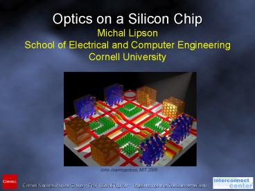
Optics on a Silicon Chip Michal Lipson School of
Electrical and Computer Engineering Cornell
University
John Joannopolous, MIT 2000
2
Lipson the advantages of using high index f
refraction contrast (confinement, high
reflectivity
Optics on a Silicon Chip
Lipson maximum of electr. Fieldby performing
refelct we were able to prove that
All-Optical Switching in Silicon
Electro-optical Switching in Silicon Coupling
from Fiber to Chip
3
Lipson the advantages of using high index f
refraction contrast (confinement, high
reflectivity
Why Silicon Nanophotonics ?
- CMOS compatibility
- Transparent at 1.3 and 1.55 ?m wavelengths
- High-index contrast compact structures
Lipson maximum of electr. Fieldby performing
refelct we were able to prove that
?
Active Devices
Modulators, switches Compact, Fast and Efficient
4
The Goal All-Optical Switching
Controlling light with light
Control (pump)
Closing gate from transparent to opaque
5
Switching in Silicon
Challenge Absence of strong switching mechanism
Mechanism Plasma Dispersion Effect Refractive
index change by free carrier injection
Weak index dependence on free carrier
concentration
Solution Strong light confinement
Small change in refractive index induces large
change in transmission properties
6
Strong Light Confining Structures
Ring Resonators
- Silicon-on-Insulator (SOI)
- E-beam lithography
- Inductively Coupled Plasma etching
Device is very sensitive to small perturbations
7
Demonstration of Silicon Closing-Switch
8
Demonstration of Silicon Opening-Switch
Pump on
0.1psec
Dt
Pump off
Pump off
Transparent
Probe
Transmission
Probe transmission
Wavelength (nm)
Opaque
Opaque
Time (ns)
9
Lipson the advantages of using high index f
refraction contrast (confinement, high
reflectivity
Optics on a Silicon Chip
Lipson maximum of electr. Fieldby performing
refelct we were able to prove that
All-Optical Switching in Silicon
Electro-optical Switching in Silicon Coupling
from Fiber to Chip
10
Silicon Electro-optic Modulator
11
Silicon Electro-optic Modulator
C. Barrios, V. Almeida, R. Panepucci, B. Schmidt,
and M. Lipson, IEEE Photonics Technology Letters,
vol 16, no. 2, 2004
12
Silicon Electro-optic Modulator
- Silicon-on-Insulator (SOI)
- E-beam lithography
- Inductively Coupled Plasma etching
- PECVD SiO2 cladding
Low Power Electro-optical Modulator
13
Ring Resonator Based Electro-Optic Modulator on
Silicon-on-Insulator
Change in resonance obtained by injecting free
carriers into the ring resonator
?n ?ne ?nh -8.8x10⁻²². ?N
8.5x10⁻¹⁸.(?P)0.8
Simulation Results
14
Fabrication
Ebeam Lithography
EBeam Resist
Si 250nm
Scanning electron micrograph of a ring resonator
BOx 3µm
Si Substrate
Width 450nm
Width 450nm
Etching using RIE
BOx 3µm
Gap 200nm
Si Substrate
Oxide Deposition
Diameter 12µm
BOx 3µm
Si Substrate
Via Hole Etching and Ion Implantation
p (B)
n (As)
BOx 3µm
Si Substrate
Microscope image of fabricated optical modulator
with electrical contacts
Contact Metallization
BOx 3µm
Si Substrate
15
Demonstration of Resonance Shift
Modulation depth up to 50 demonstrated at ?
1550nm
16
Lipson the advantages of using high index f
refraction contrast (confinement, high
reflectivity
Optics on a Silicon Chip
Lipson maximum of electr. Fieldby performing
refelct we were able to prove that
All-Optical Switching in Silicon
Electro-optical Switching in Silicon Coupling
from Fiber to Chip
17
Coupling Problem
Optical Fiber
Mode-size mismatch
3 Transmission
Effective index mismatch
18
Proposed Solution
sub-micron
microns
tens of microns
- Same mode-size
- Same effective index
- Same mode-size
19
Mode Conversion
90 efficiency in 40?m?(FDTD) ? 0.46 dB of
coupler insertion losses
20
Results
Coupler Insertion Losses 3 dB (TM) and 6 dB
(TE) Only 0.5 dB loss for 1 micron misalignment
- E-beam lithography
- Plasma etching
- SiO2 cladding (PECVD)
V. Almeida, R. Panepucci, and M. Lipson, Optics
Letters, vol. 28, pp. 1302, 2003
21
Conclusions
Demonstration of the following A compact, low
power all-optical silicon switch Compact, low
power electro-optical modulators A compact,
highly efficient nanotaper fiber to chip coupler
Recommended
CrystalGraphics Presentations


