
Initial and Advanced LIGO Detectors - PowerPoint PPT Presentation
1 / 44
Title: Initial and Advanced LIGO Detectors
1
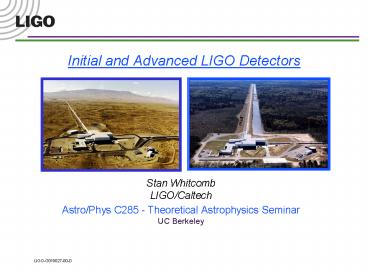
Initial and Advanced LIGO Detectors
- Stan Whitcomb LIGO/Caltech
- Astro/Phys C285 - Theoretical Astrophysics
SeminarUC Berkeley
2
Outline of Talk
- Initial Detector Overview
- Performance Goals
- How do they work?
- What do the parts look like?
- Very Current Status
- Installation and Commissioning
- Advanced LIGO Detectors
3
LIGO Observatories
4
Hanford Observatory
5
Livingston Observatory
6
Initial DetectorsUnderlying Philosophy
- Jump from laboratory scale prototypes to
multi-kilometer detectors is already a BIG
challlenge
- Design should use relatively cautious
extrapolations of existing technologies - Reliability and ease of integration should be
considered in addition to noise performance - The laser should be a light bulb, not a research
project Bob Byer, Stanford - All major design decisions were in place by 1994
- Initial detectors would teach us what was
important for future upgrades - Facilities (big ) should be designed with more
sensitive detectors in mind - Expected 100 times improvement in sensitivity is
enough to make the initial searches interesting
even if they only set upper limits
7
Initial LIGO Interferometers
Michelson Interferometer
end test mass
Laser
beam splitter
signal
8
Initial LIGO Sensitivity Goal
- Strain sensitivity lt3x10-23 1/Hz1/2at 200 Hz
- Sensing Noise
- Photon Shot Noise
- Residual Gas
- Displacement Noise
- Seismic motion
- Thermal Noise
- Radiation Pressure
9
Initial LIGO Detector Status
- Construction project - Finished
- Facilities, including beam tubes complete at both
sites - Detector installation
- Washington 2k interferometer complete
- Louisiana 4k interferometer complete
- Washington 4k interferometer in progress
- Interferometer commissioning
- Washington 2k full interferometer functioning
- Louisiana 4k individual arms being tested
- First astrophysical data run - 2002
10
Vibration Isolation Systems
- Reduce in-band seismic motion by 4 - 6 orders of
magnitude - Large range actuation for initial alignment and
drift compensation - Quiet actuation to correct for Earth tides and
microseism at 0.15 Hz during observation
11
Seismic Isolation Springs and Masses
12
Seismic System Performance
HAM stack in air
BSC stackin vacuum
13
Core Optics
14
Core Optics Requirements
- Substrates
- 25 cm Diameter, 10 cm thick
- Homogeneity lt 5 x 10⁻⁷
- Internal mode Qs gt 2 x 10⁶
- Polishing
- Surface uniformity lt 1 nm rms
- ROC matched lt 3
- Coating
- Scatter lt 50 ppm
- Absorption lt 2 ppm
- Uniformity lt10-3
- Successful production eventually involved 6
companies, NIST and the LIGO Lab
15
Core Optic Metrology
- Current state of the art 0.2 nm repeatability
LIGO data (1.2 nm rms)
CSIRO data (1.1 nm rms)
16
Core Optics Suspension and Control
17
Core Optics Installation and Alignment
18
Pre-stabilized Laser
- Deliver pre-stabilized laser light to the 15-m
mode cleaner - Frequency fluctuations
- In-band power fluctuations
- Power fluctuations at 25 MHz
- Provide actuator inputs for further stabilization
- Wideband
- Tidal
Tidal
Wideband
4 km
15m
10-Watt Laser
Interferometer
Modecleaner
PSL
10-1 Hz/Hz1/2
10-4 Hz/ Hz1/2
10-7 Hz/ Hz1/2
19
Washington 2k Pre-stabilized Laser
Custom-built 10 W NdYAG Laser
Stabilization cavities for frequency and beam
shape
20
WA 2k Pre-stabilized Laser Performance
- gt 20,000 hours continuous operation
- Frequency lock very robust
- TEM00 power gt8 W delivered to input optics
- Non-TEM00 powerlt 10
- Improvement in noise performance
- electronics
- acoustics
- vibrations
21
LIGO Interferometers
Requires test masses to be held in position to
10-10-10-13 meter Locking the interferometer
end test mass
Light bounces back and forth along arms about 100
times
Light is recycled about 50 times
input test mass
Laser
signal
22
Steps to Locking an Interferometer
Y Arm
Laser
X Arm
signal
23
Watching the Interferometer Lock
Y Arm
Laser
X Arm
signal
24
Lock Acquisition Example
Carrier Recycling Gain 10
Sideband Recycling Gain 5
25
Full Interferometer Locking
90 Minutes
26
First Interferometer Noise Spectrum
Recombined Michelson with F-P Arms (no recycling)
November 2000
Factor of 105 106 improvement required
27
Improved Noise Spectrum
- 9 February 2001
- Improvements due to
- Recycling
- Reduction of electronics noise
- Partial implementation of alignment control
28
Known Contributors to Noise
New servo to improve frequency stabilization
installed last week Testing is underway
29
Advanced LIGO
- Now being designed by the LIGO Scientific
Collaboration - Goal
- Quantum-noise-limited interferometer
- Factor of ten increase in sensitivity
- Factor of 1000 in event rate. One day gt
entire2-year initial data run - Schedule
- Begin installation 2006
- Begin data run 2008
30
Facility Limits to Sensitivity
- Facility limits leave lots of room for future
improvements
31
Present and future limits to sensitivity
- Advanced LIGO
- Seismic noise 40?10 Hz
- Thermal noise 1/15
- Shot noise 1/10, tunable
- Facility limits
- Gravity gradients
- Residual gas
- (scattered light)
- Beyond Adv LIGO
- Thermal noise cooling of test masses
- Quantum noise quantum non-demolition
32
Advanced Interferometer Concept
- Signal recycling
- 180-watt laser
- Sapphire test masses
- Quadruple suspensions
- Active seismic isolation
- Active thermal correction
33
Anatomy of Projected Performance
- Sapphire test massbaseline system
- Silica test mass dotted line
- Seismic cutoff at 10 Hz
- Suspension thermal noise
- Internal thermal noise
- Unified quantum noise dominates at most
frequencies - technical noise (e.g., laser frequency)
levels held in general well below these
fundamental noises
34
System trades
- Laser power
- Trade between improved readout resolution, and
momentum transfer from photons to test masses - Distribution of power in interferometer optimize
for material and coating absorption, ability to
compensate - Test mass material
- Sapphire better performance, but development
program, crystalline nature - Fused silica familiar, but large, expensive,
poorer performance - Lower frequency cutoff
- Technology thresholds in isolation and suspension
design
35
Nominal top level parameters
36
Tailoring the frequency response
- Signal Recycling
- Additional cavity formed with mirror at output
- Can be resonant, or anti-resonant, for
gravitational wave frequencies - Allows optimum for technical limits,
astrophysical signatures - Advanced LIGO configuration
37
Advanced Core Optics
- A key optical and mechanical element of design
- Substrate absorption, homogeneity, birefringence
- Ability to polish, coat
- Mechanical (thermal noise) performance,
suspension design - Mass to limit radiation pressure noise 30-40
Kg required - Two materials under study, both with real
potential - Fused Silica very expensive, very large,
satisfactory performance familiar,
non-crystalline - Sapphire requires development in size,
homogeneity, absorption high density (small
size), lower thermal noise
38
Sapphire substrate homogeneity
- CIT measurement of a 25 cm m-axis sapphire
substrate, showing the central 150mm - The piece is probed with a polarized beam the
structure is related to small local changes in
the crystalline axis - Plan to apply a compensating polish to side 2 of
this piece and reduce the rms variation in bulk
homogeneity to roughly 10-20 nm rms
39
SEI Conceptual Design
- Two in-vacuum stages in series, external slow
correction - Each stage carries sensors and actuators for 6
DOF - Stage resonances 5 Hz
- High-gain servos bring motion to sensor limit in
GW band, reach RMS requirement at low frequencies - Similar designs for both types of vacuum chamber
provides optical table for flexibility
40
Global Network of GW Detectors
GEO
Virgo
LIGO
TAMA
AIGO
41
GW Detectors
AIGO Australia
GEO 600 Germany
Virgo Italy
42
GW Detectors
TAMA 300 Sensitivity
TAMA 300 Japan
LCGT - Kamioka
43
Event Localization with Array of Detectors
Dq c dt / D12 Dq 0.5 deg
44
Where do we go from here?
- 2001
- Detector commissioning
- First coincidence operation
- Improve sensitivity/ reliability
- Initial data run (upper limitrun)
- 2002
- Begin Science Run
- Interspersed data taking and machine
improvements - Advanced LIGO RD
First Lock in the Hanford Observatorycontrol
room
Recommended
CrystalGraphics Presentations


