
Force Analysis - PowerPoint PPT Presentation
1 / 30
Title: Force Analysis
1
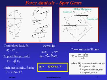
Force Analysis Spur Gears
2
Force Analysis Helical Gears
3
Force Analysis Bevel Gears
? Pressure angle (20o)
4
Force Analysis Worm Gear Sets
Three orthogonal components of W without
considering friction
5
Force Analysis Worm Gear Sets
Two useful relations, friction force and
transmitted loads.
6
Stress Analysis Spur Gears
Bending Strength
Lewis equation (1892 Wilfred Lewis, Philadelphia
Engineers Club)
W t
F
7
Modification of Lewis Equation
Assumptions made in deriving Lewis equation
- The load is applied to the tip of a single tooth.
- The radial component of the load, Wr , is
negligible.
- The load is distributed uniformly across the full
face width.
- Stress concentration in the tooth fillet is
negligible.
8
Modification of Lewis Equation
Modifications according to AGMA standards
(American Gear Manufacturers Association)
Lewis equation
W t tangential transmitted load Ka application
factor KV dynamic factor KS size factor KI Idler
factor (use 1.42 if designing an idler
gear) Pd transverse diameteral pitch F face width
of the narrower member Km load-distribution
factor KB rim-thickness factor J geometry factor
for bending strength which includes root fillet
stress concentration factor Kf
9
Bending Stress Modifying Factors
Geometry factor J
10
Bending Stress Modifying Factors
Dynamic factor Kv
11
Bending Stress Modifying Factors
Size factor Ks
AGMA has not established standards for size
factor and recommends that Ks be set to 1.
12
AGMA Bending Strength Equation
Allowable Stress
Sfb is the allowable fatigue bending stress, psi
KL is life factor
KT is the temperature factor
KR is the reliability factor
13
AGMA Bending Strength Equation
Stress cycle factor KL
14
AGMA Bending-Fatigue Strength, Sfb
15
Surface Strength Analysis
The basic surface deterioration
Scoring
If the surface asperity welding and tearing cause
a transfer of metal from one surface to the
other, the resulting surface damage is called
scoring. If the local welding of asperities
becomes so extensive that the surfaces no longer
slide on each other, the resulting failure is
called seizure.
16
Surface Strength Analysis
Abrasive wear
Abrasive wear is a surface damage caused by the
presence of abrasive particles in the lubricant.
Large particles tend to scratch and gouge the
surface, where small (dust like) particles polish
the tooth surface to a mirror finish.
Scoring, abrasive wear and corrosion wear are due
to the failure of lubrication system.
17
Surface Strength Analysis
Surface Fatigue Failure, due to repeated contact
load
Proper lubricating system can minimize the
surface damage due to wear and corrosion. But,
surface fatigue can occur even with proper
lubrication and its the most common mode of gear
failure and is characterized by pitting and
spalling of the tooth surface. The damage is
caused by repeated contact stresses.
18
AGMA Surface Stress Equation
Cp elastic coefficient, (lb/in2)0.5 Wt transmitted
tangential load Ca overload factor (same as
Ka) Cv dynamic factor (same as Kv) Cs size factor
(same as Ks) Cm load-distribution factor (same as
Km) Cf surface condition factor d pitch diameter
of the pinion F face width of the narrowest
member I geometry factor
19
AGMA Surface Stress Equation
AGMA Elastic coefficient CP
20
AGMA Surface Strength Equation
Sfc is the allowable contact stress, psi
CL is the surface-life factor
CT is the temperature factor (same as KT)
CR is the reliability factor (same as KR)
CH is the hardness ratio factor
21
AGMA Surface Strength Equation
Pitting resistance stress cycle factor ZN
22
AGMA Surface Strength Equation
AGMA allowable surface fatigue strength
23
AGMA Spur Gear Design Equations
Surface strength design equation, Stress
strength
Design steps
- Calculate the transmitted load
- Select material, start with grade 1 with low
hardness.
- Select standard full depth gears with pressure
angle of 20o or 25o.
- Choose a face width, ½ dP F dP
- Decide on load type (uniform, non-uniform),
mounting accuracy, of cycles to failure, gear
quality and reliability.
- Solve the design equation for the diameter.
- Or, select diameter and solve for material.
24
AGMA Spur Gear Design Equations
Bending strength design equation
Design steps
- Assume a value for J (geometry factor), .35 to .45
- Solve the design equation to obtain the diametral
pitch, Pd
- Calculate the number of teeth for pinion and
gear, determine the actual J and check against
the assumed one, iterate if needed.
- The number of teeth on the pinion should be over
18 to avoid interference.
- For power transmission, 2 lt Pd (diametral pitch)
lt 16
- Iterate until optimum design is achieved.
25
Design Example
Design a pair of spur gears to transfer power
from a 25 hp motor to a fan. The motor turns at
1000 rpm and the desired fan speed is 500 rpm.
Specify the material, diameter, and number of
teeth for both gears.
- Assume good quality gear with, Qv 10, will be
used.
- Select face width F dP (pinion diameter) ,
dP/2 F dP
- Assume operating temp. less than 250o (KTCT
1), new gear (Cf 1), and a small size gear
(KsCs 1).
26
Design Example
Surface failure
27
Design Example
Pitch line velocity, ft/min.
Wt (1.26 x 10⁵) 25 / dP 1000
V p d ? / 12
Wt 3150 / dP
Assume dynamic factor C v .9 and load
distribution factor Cm 1.6 Both assumptions
have to be checked later.
2300(3150/dP)(1/.9)(1.6)(1/.107)(1/dp)21/2
125,000
28
Design Example
V (p dP ?P)/12 p x 2.6 x 1000/12 V 680
ft/min
With these corrections, dP 2.6
29
Design Example
Bending failure
For A-3 material, St 36,000 47,000 psi Use
36,000 psi in calculation
Assume J .4, check later
For power transmission, 2 P 16, so select
P 16
30
Design Example
Check assumption for J
NP P dP 16 x 2.75 44
NG P dG 16 x (2.75x2) 88
J .43
P 19.7
So P 16 is valid
Recommended
CrystalGraphics Presentations


