
6mm - PowerPoint PPT Presentation
1 / 1
Title: 6mm
1
? Development of Readout Electronics for MPPC ?
Takeshi.Murakami,Shinichi.Gomi
KEK,Department of Physics, Kyoto University
We report the read out electronics of MPPC(
Multi-Pixel Photon Counter ). MPPC is a new
photodetector developed by Hamamatsu Photonics.
Here, we report Trip-t ASIC chips and those
electronics. We report the read out
electronics, Trip-t Test Board. MPPC and Trip-t
chip have been decided to use in T2K experiment.
We now test the basic performances of latest MPPC
samples, and check the device-by-device variation
about many samples with Trip-t Test Board. Trip-t
Test Board can be used for reading out signals
from 32 MPPC at the same time.
Trip-t readout sequence
MPPC ( Multi-Pixel Photon Counter )
- Multi-Pixel Photon Counter ( MPPC ) is a new
type of photo detector developed by Hamamatsu
Photonics (HPK). - MPPC consists of 1001600 small avalanche photo
diodes( APD ) in 1mm1mm sensitive region.
MPPC SIGNAL(CH1)
The injected charge to each channel is amplified
by the front-end amplifiers and stored in
pipeline before readout. Next the stored signals
are serialized to 1 channel by multiplexer which
is located at the last stage of Trip-t. Using 1
Trip-t, we can reduce the number of readout
channels from 32 to 1. Simply speaking, A_OUT
corresponds to the amplitude of input charge,
T_OUT corresponds to the timing of input charge
and D_OUT corresponds to the digital information
of input charge.
Pre-AMP RESET
6mm
Pre-AMP after MPPC signal
- MPPC advantages
- Compact
- Insensitive to magnetic field
- High gain( 106 ), low bias voltage( 70V )
- High photon detection efficiency
- Excellent photon counting capability
0
1
2
32
1pixel
CLOCK(mux)
A_OUT
MPPC Signal
T_OUT
D_OUT
Sensitive region of MPPC
Trip-t chip
Pipeline Clock
Voltage
time
Developed by FNAL Used in D0 experiment
Plan to use in T2K experiment and MINERvA
experiment Input 32ch Analog signal ( -
) Output
VME6U DAQ Board
VME IF FPGAXC95144XL-TQ144
- Discri signal of each 32ch
- Analog signal proportional to input signal
- Analog signal proportional to the time between
input signal and gate signal
The DAQ(Data AcQuisition) board is a VME standard
module and was originally developed for the
SciBar detector in K2K experiment. We use this
DAQ board for an analog-to-digital conversion of
A_OUT from Trip-t. Several modifications are
made to the DAQ board in order to adjust it to
the readout of MPPCs.
VME SIDE
J0
FPGAXC3S400PQ208
ADCAD9220
Total 128pins
Trip-t MPPC Mount Board
- Since A_OUT of Trip-t has 1.0V DC offset, we put
A_OUT to the outm of the DAQ board and DC1V to
the outp. By subtracting the outp from the outm,
A_OUT has no offset. - We change the gain of DAQ board from 20 to 1
because the gain of the Trip-t is enough high.
MPPC Hole 5.3f (32 Mount)
DACMAX529
Labview
Trip-t Position
TRG-A
TRG-B
BUSY
TA-B
TA-A
CLK
40pin connector2
Distal wave generator
Trip-t Performances
5VIN
Bias control
Bias control
Input charge versus. ADC count
Linearity
Cross-talk
155mm
High Gain
When the gain of Trip-t is high, linearity become
wrong at low charge region.
190mm
Check the signal cross-talk to the another input
channel. Cross-talk is small enough.
190mm
Those 2 boards, Labview and VME are connected by
flat cable.
65mm
Low Gain
0.4
MPPC Mount Side
Trip-t Mount Side
MPPC Mount Board with 32 MPPC
Input only No.15 channel
with Plastic Connector for connecting MPPC to
wave length shifting fiber
Trip-t Test Board for Measurement
KEK Trip-t Board Block Diagram
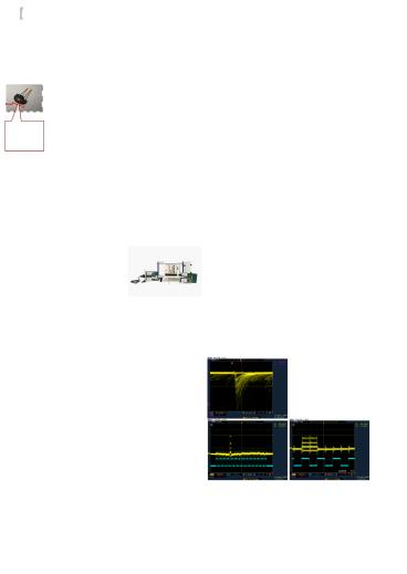
The left figure is MPPC raw signal. MPPC has good
photon counting capability. By using Trip-t Test
Board, we are now measuring about the basic
performances and device-by-device variation of
MPPC for T2K experiment.
Pedestal
Trip-t power supplies
1PE
VDDD(digital)2.5V , VDDA(analog)2.5V
2PE
OPAMP power supplies ???5V
3PE
When we use all 32 channel, each output come at
each MUX positions as those figure.
Power supply
MPPC raw signal
5V
-5V
Input to 10CH
Regulator
5V ? 2.5V
3PE
2PE
VME
Trip-t
OPAMP
1PE
Pedestal
10
11
12
13
1?2?3?4?5?6?7?8?9?10?11???
???31?32?33
Trip-t Block Diagram
for testpulse
ch2
Example of Histogram by Trip-t
Basic performances of MPPC
Serialize
Pedestal
For T2K experiment, 60000 samples of MPPC must
be measured. By this test board, we can measure
32 MPPCs at the same time. Now, we construct the
system for mass production of MPPC samples for
T2K experiment with this 32ch test board.
1PE
2PE
3PE
Finally, we would like to express our thanks to
T.Nakaya, M.Yokoyama, M.Taguchi (Kyoto
University), J.Haba, T.Nakadaira (KEK FDG), and
M.Tanaka (KEK Electronics Group) for supporting
the study.
? PD07 ? - International Workshop on new
photon-detectors- _at_ Kobe University, JAPAN
June 27-29, 2007
Recommended
CrystalGraphics Presentations


