
Presentazione di PowerPoint - PowerPoint PPT Presentation
1 / 17
Title:
Presentazione di PowerPoint
Description:
1. Use of optical fiber sensors (Fiber Bragg Grating) for continuous and real ... Cantilever like' disposition. Micrometric screw for imposing tip displacement. ... – PowerPoint PPT presentation
Number of Views:33
Avg rating:3.0/5.0
Title: Presentazione di PowerPoint
1
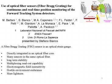
- Use of optical fiber sensors (Fiber Bragg
Grating) for continuous and real-time position
monitoring of the Forward Tracking System
detectors. - M. Bertani 1, S. Bianco 1, M.A. Caponero 2,1,?,
F.L. Fabbri 1, F. Felli 3,1, M. Giardoni 1,A. La
Monaca 1, E. Pace 1, M. Pallotta 1, A. Paolozzi
3,1 - Laboratori Nazionali di Frascati dellINFN
- ENEA Frascat1
- Univ. Di Roma La Sapienza
- presented by Stefano Bianco
- A Fibre Bragg Grating (FBG) sensor is an optical
strain gauge. - Directly integrated in an optical fiber core.
- Many sensors in the same optical fiber.
- long term stability
- Multiplexing read-out capability
- Electromagnetic field insensitivity
- Hostile environment endurance
- Mass lightness.
2
- FBG sensor operating principle
- phase diffraction grating along the fibre axis.
- Principle of operation based on spectroscopy.
- Light propagating in the optical fibre is
diffracted (back-reflected) by FBG. - Diffraction is wavelength selective.
- Diffracted wavelength depends on FBG geometry,
that is affected by stress.
Typical values Ds 1me ? Dl 1pm
3
Deformation of a structure can be monitored by
embedded FBGs.
Stuck FBG
Structure at rest FBG signal
l
l0 l(s0)
Monitored structure
Stressed structure FBG signal
l
l1l(s1)
l0
4
Monitoring the displacements of a detector
relative to a reference frame
- Conceptual mechanical design for straw/microstrip
station stable massive frame holding in place
slight detectors. - Slight specimen is positioned in steel frame by
three axially strained braces. - Braces are provided with cardan joints to avoid
bending and torsion.
5
One FBG is glued on each brace to provide axial
brace deformation monitoring. Specimen
displacement is worked out by the signal of
FBGs. Specimen is displaced pulling/pushing the
specimen along perpendicular directions.
6
Specimen displacement is monitored by microscope
lens with 2mm resolution.
7
Monitoring the displacement due to a step
increasing force in the X direction
FBG wavelength shift (strain of instrumented
braces)
8
Monitoring the displacement due to a step
increasing force in the X direction
Comparison of X displacement worked out by signal
of FBGs and detected by TV camera
9
Monitoring the displacement due to a step
increasing force in the X direction
Comparison of Y displacement worked out by signal
of FBGs and detected by TV camera
10
Long term monitoring the displacement due to
environment temperature
filestack 020819_24
FBG wavelength shift (strain of instrumented
braces)
11
Long term monitoring the displacement due to
environment temperature
filestack 020819_24
Comparison of X displacement worked out by signal
of FBGs and detected by TV camera
12
One FBG sensor on the surface of a slab does not
allow for discriminating Axial deformation from
Bending.
Two FBG sensors on the opposite surfaces of a
slab allow for discriminating Axial deformation
from Bending.
- Bending
- FBGs experience opposite strain
- Axial deformation
- FBGs experience the same strain.
13
Two sensors embedded in a Carbon Fiber Reinforced
Plastic (CFRP) slab made by 8 pre-peg
fabrics. Sensors simmetricaly placed above and
under the neutral axis of the slab. Axial
deformation and Bending of the slab can be
monitored.
Carbon fiber fabrics Optical fiber
14
Cantilever like disposition. Micrometric screw
for imposing tip displacement. Optical
comparator for displacement monitoring.
15
Experimental data obtained for a step-by-step
tip displacement with 0.2mm increment. Linear
fit of data show that tip displacement can be
monitored with ?0.05mm resolution (versus of
bending is discriminated).
Obtained resolution strictly depends on the
adopted geometry (it can be improved if FBG
sensors are moved away from the neutral axis)
16
- Bending test periodically repeated to verify
long-term stability and temperature dependence.
- No temperature dependence has been found
- long-term stability applies
17
- CONCLUSIONS
- FBG sensors provide efficient real-time and
long-term monitoring of structure deformations. - Axial deformation and Bending can be effectively
discriminated, allowing for monitoring both
in-plane and out-of-plane displacements. - FBG sensors can be efficiently embedded in CFRP
components, thus providing detector supporting
structure with built-in structural monitoring
system. - Results of experimental tests on a 50cm x 50cm
mock-up show that specimen position can be
monitored with resolution - Better than 1.0mm for in-plane displacement (X,Y)
- Much better than 50mm for out-of-plane
displacement (Z)