
Transistors - PowerPoint PPT Presentation
1 / 21
Title:
Transistors
Description:
The switch current can be controlled by either current or voltage ... Type of. Amplifier. Typical Input and Output Impedances of. Different types of Amplifiers ... – PowerPoint PPT presentation
Number of Views:182
Avg rating:3.0/5.0
Title: Transistors
1
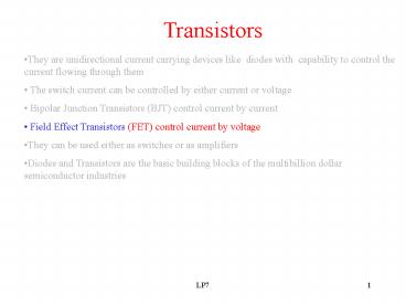
Transistors
- They are unidirectional current carrying devices
like diodes with capability to control the
current flowing through them - The switch current can be controlled by either
current or voltage - Bipolar Junction Transistors (BJT) control
current by current - Field Effect Transistors (FET) control current
by voltage - They can be used either as switches or as
amplifiers - Diodes and Transistors are the basic building
blocks of the multibillion dollar semiconductor
industries
2
MOSFET Metal Oxide Semiconductor Field Effect
Transistor
- A voltage controlled device
- Handles less current than a BJT
- Two types NMOS and PMOS
- Easier to manufacture
3
MOSFET Structure
4
N-Channel MOSFET Symbol
- D Drain, S Source, G Gate, B Body
- Normally Body and Source are shorted internally
- Drain current is controlled by controlling Gate
to Source Voltage
5
Biasing N-Channel MOSFET
6
Biasing N-Channel MOSFET (2)
7
Conduction of N-Channel MOSFET
8
Output Characteristics of N-Channel MOSFET
Triode region of MOSFET is equivalent to
saturation region of BJT Saturation region of
MOSFET is equivalent to Active region of BJT
9
Relationship between Drain Current and Gate to
Source Voltage of MOSFET
In Triode Region iD K 2(vGS-Vto)vDS-v2DS In
Saturation Region iD K (vGS-Vto)2 At the
Boundary between the Triode and Saturation
Region iD K v2DS (How?) K Device Constant
which can vary from device to device
10
Fixed Plus Self Bias Circuit
A Good circuit to establish stable Q point that
is relatively independent of device parameter
Gate Current iG 0 (why?)
11
To Find iD and VGS in a Fixed Plus Self Bias
Circuit
- The circuit operates in
- Saturation Mode
- Discard the extraneous root
- iD and VGS can also be obtained
- by solving the quadratic equation involving iD
or VGS that can be - obtained using 12.12 or 12.13
- (see example 12.2)
Equation 12.12
Equation 12.13
12
Common Source Amplifier
(Analogous to Common Emitter Amplifier)
13
Small-Signal Equivalent Circuit Of MOSFET
14
Reason for Modification of Small-
Signal Equivalent Circuit Of MOSFET
15
Derivation of the Small-Signal Equivalent
Circuit of MOSFET on the Greenboard
16
Small Signal AC Equivalent Circuit for Common
Source Amplifier
17
Derivation of the Av etc. of the CS amplifier on
the Greenboard
18
Source Follower
(Analogous to Emitter Follower)
19
Small Signal AC Equivalent Circuit for Source
Follower
20
Derivation of the Av etc. of the Source Follower
on the Greenboard
21
Typical Input and Output Impedances of Different
types of Amplifiers
Recommended
CrystalGraphics Presentations


