
Performances of the upgraded SVT - PowerPoint PPT Presentation
1 / 1
Title:
Performances of the upgraded SVT
Description:
Bigger AM Need faster HIT-PATTERN association new Hit Buffer (HB ... than 50 s can cause all the Level 2 buffers to be filled and therefore deadtime ... – PowerPoint PPT presentation
Number of Views:18
Avg rating:3.0/5.0
Title: Performances of the upgraded SVT
1
The Silicon Vertex Trigger upgrade at
CDF J.Adelman1, A.Annovi2, M.Aoki3, A.Bardi4,
F.Bedeschi4, S.Belforte5, J.Bellinger6,
E.Berry1,M.Bitossi2, M.Bogdan1, M.Carlsmith6,
R.Carosi4, P.Catastini9, A.Cerri8, S.Chappa7,
W.Chung6,M.A.Ciocci9, F.Crescioli2, M.Dell
Orso2, B.Di Ruzza11, S.Donati2, I.Furic1,
S.Galeotti4, P.Giannetti4, C.M.Ginsburg6,
P.Giovacchini4, R.Handler6, Y.K.Kim1, J.D.Lewis7,
T.Liu7, R.Mahlum7, T.Maruyama3, F.Morsani4,
G.Ott6, I.Pedron10, M.Piendibene4, M.Pitkanen7,
L.G.Pondrom6, G.Punzi2, B.Reisert7, M.Rescigno11,
L.Ristori4, H.Sanders1, L.Sartori10,
F.Schifano10, F.Sforza9, M.Shochet1, B.Simoni2,
F.Spinella4 , P.Squillacioti9, F.Tang1, S.Torre9,
R.Tripiccione10, G.Volpi9, U.K.Yang1,
L.Zanello11, A.M.Zanetti5 1University of
Chicago,Illinois,USA, 2University of Pisa, Italy,
3University of Tsukuba,Japan, 4INFN Sezione di
Pisa, 5INFN Sezione di Trieste, 6University of
Wisconsin,USA, 7Fermilab,Batavia,Illinois,USA,
8LBL,California,USA, 9University of Siena,Italy,
10University of Ferrara and INFN,Italy,
11University of Rome and INFN,Italy
7.6 MHz Crossing rate
CDF DAQ Trigger
- The Silicon Vertex Trigger reconstructs in real
time tracks precise enough to measure b quark
decay secondary vertices. - The tracks reconstructed by SVT are used for the
selection of events at the Collider Detector at
Fermilab (CDFII) - The CDF DAQ and Trigger system is organized in
three levels. The Level 2 uses the SVT tracks for
the event selection - The Level-2 Trigger processing time at present
limits the Level-1 bandwidth depending on
instantaneous luminosity. The SVT takes a
significant fraction of the total Level-2
processing time whose fluctuations cause deadtime
and limit the Level-2 processing rate
Finding tracks in the silicon
Detector Raw Data
Design goals
- Level 1
- 7.6 MHz Synchromous Pipeline
- 5544 ns Latency
- 50 KHz accept rate
20 kHz actual
- 40 kHz accept rate
SVT here
Level 1 pipeline 42 clock cycles
Level 1 Trigger
- The task of the Silicon Vertex Trigger (SVT) is
very complex - Links hits from five layers of the Silicon Vertex
Detector (SVX) to segments observed in the
Central Outer Chamber (COT) - The task proceeds through steps of increasing
resolution. - Associate hits to tracks at low resolution
(roads) strongly reducing the combinatorics - Fit tracks and precisely determine their
parameters solving the residual combinatorics - Thanks to the use of Associative Memories the
first step is performed in parallel during the
detector readout
- Level 2
- Asynchronous 3 Stage Pipeline
- 20 ?s Latency
- 300 Hz accept rate
- 20 ?s average Latency
35 ?s actual
COT tracks
SVX hits
L1 Accept
- 2 steps
- Find tracks _at_ low resolution not time consuming
- Fit hits at full res. time consuming depending
on the number of fits
Level 2 Trigger
Low res track
Level 2 buffer 4 events
300?m
L2 Accept
Tails are important
DAQ buffers
L3 Farm
To Mass Storage (50100 Hz)
1st Pulsar Sequencer Road warrior (AMS/RW)
Associative Memory 512 kpattern (AM)
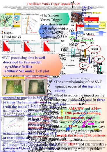
- Why was the SVT upgrade necessary?
- SVT processing time is well described by this
model c1(35ns)N(Hit) (300ns)N(Comb.). Left
plot shows comparison between this
parameterization (blue line) and data (red
histogram) taken at 5x1031cm-2s-1. The two
histograms agree. - The peak luminosity the Tevatron is expected to
provide is 30x1031cm-2s-1 (6 times the luminosity
used to train the model). Middle plot shows the
expected performances of the SVT at the maximum
luminosity. 56 of events would take longer than
50?s to be processed a time long enough for all
Level 2 buffers to be filled. Impossible to run
SVT at that luminosity. - To reduce the processing time
- Thinner patterns ? less fits but bigger AM
(AM) - Bigger AM ? Need faster HIT-PATTERN
association ? new Hit Buffer (HB) - Faster Fits ? new Track Fitter (TF)
- Rightmost plot shows how the 512k pattern AM bank
and TF reduce the tails - The two steps upgrade
- First install AM, AMS/RW, TF allow for 128k
pattern bank. AM inherited from FTK. TF and
AMS/RW implemented in Pulsar - Second step faster HB in another pulsar to
support the final 512k pattern bank.
3rd Pulsar Track Fitter (TF)
2nd Pulsar Hit Buffer (HB)
- Phased installation of the SVT upgrade
- The commissioning of the SVT upgrade occurred
during data taking - Need to reduce the impact on the data
acquisition proceed in three phases - Install AMS/RW and AM with 128k patterns
enabling only 32k patterns major changes to the
SVT crate layout - Install TF and after few days of data taking
without problem enable the whole 128k patterns
bank (July 2005) - Install HB and after few days of data taking
without problem enable the whole 512k patterns
bank (February 2006) - System fully tested before installation of any
board - Standalone test of each board check firmaware
functionality and develop the software for
monitoring and debugging - Vertical slice tests create a whole SVT crate
with new boards and feed it with data coming from
one SVT wedge to compare the output of old and
new system - Take data with one upgraded wedge before
proceeding to the full installation we install
the new boards in one wedge and take data for at
least 100 hours - Most of the data taken during the commissioning
were good
Performances of the upgraded SVT
Effect of the upgrade on the DAQ The deadtime as
a function of the rate of events accepted by the
Level 1 (L1A) shows the upgrade impact on the
performance of the DAQ. The upgrade reduces the
deadtime allowing for higher output rates at
Level 1
- Mean processing time
- The average processing time of old SVT used to
have a large growth at high luminosity. - The faster hardware
- allows for smaller mean processing time
- reduces the dependence on the instantaneous
luminosity - The new system allows for a smaller latency at
Level 2
- Fluctuations of the processing time
- Large processing times measured by the
distribution RMS are due to complex events - They are reduced by improving the fitting stage
- The TF fits each hit combination in less time,
reducing the dependence on the number of
combination (175 ns instead of 300 ns) - The larger pattern bank allow for thinner road
and consequently a smaller number of combination
to be fitted per road - The upgrade reduce the dependence of the
fluctuations on the luminosity providing a larger
Level 1 bandwidth over a wide luminosity range
B triggers
- Fraction of long processing time events
- Events with processing time higher than 50?s can
cause all the Level 2 buffers to be filled and
therefore deadtime - The percentage of this kind of events used to be
strongly dependent on the instantaneous
luminosity - The upgrade reduces the fraction of long
processing time events and its dependence on the
instantaneous luminosity - With 512k patterns at luminosity of
1.5x1031cm-2s-1 less than 2 of events require
more than 50?s to be processed
- At low luminosity the bandwidth is mostly filled
by B physics triggers - The 128 kpattern bank already allowed to
increase the minimum Level 1 Accept rate at low
luminosity from ?20 kHz (blue) to ?25 kHz
(violet). - With the 128 kpattern bank we can already
collect 20 more of B decays than in the past
with negligible deadtime - Because of the shutdown no significant
comparison with fully upgraded SVT is possible
yet at high luminosities, but the power of the
system has been strongly improved (see plots on
the left) to be ready for the highest
luminosities . - Thanks to the upgrade, CDF will be able to fully
exploit the increase of the Tevatron luminosity
and efficiently select events containing
displaced vertexes