
Reentrant Functions - PowerPoint PPT Presentation
1 / 11
Title:
Reentrant Functions
Description:
... to produce the effect of a red ball that constantly bounces back and forth. ... specify eight different speeds for the bouncing ball, and the user can change ... – PowerPoint PPT presentation
Number of Views:220
Avg rating:3.0/5.0
Title: Reentrant Functions
1
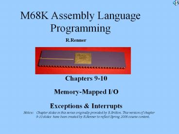
Chapters 9-10 Memory-Mapped I/O Exceptions
Interrupts
Notice Chapter slides in this series
originally provided by B.Britton. This version of
chapter 9-10 slides have been created by
R.Renner to reflect Spring 2006 course content.
2
Memory-Mapped I/O
- Mechanism used to communicate with external (to
processor) devices - M68K move instructions w/absolute long address
- Address corresponds to a device register
- Device connected to system bus, like CPU and
memory (see figure 9.1) - Processor can both inquire and modify state of
connected device, simply
Renner slide
3
System Bus with Typical Keyboard/Display
Interface
M68K CPU
Main Memory
Read-only
Control KEYBOARD Data (2 8-bit
registers)
Interrupt Enable
Ready
Read-only
Read-only
Control DISPLAY Data (2 8-bit registers)
Interrupt Enable
Ready
Write-only
Fig.9.1 from Britton text
Disk Controller
Renner slide
Ethernet Controller
4
Device Controllers
- Provide interface protocol for programmers
- Provide registers for communication
- Number of available device (receiver) registers
grows with complexity
Renner slide
5
Keyboard Controller
- Method 1 polling
- gt ready bit (lsb) interrupt enable bit
- Keypress load data register with key value,
ready bit with 1 - Example mapping (assume byte addresses are
E00100 and E00101) - CkKEYBD
- move.b E00100,D0 Read from kbrd control
register - btst.b 0,D0 Test kbrd ready bit (bit 0)
- beq CkKEYBD Branch if ready bit D0 equals 0
- move.b E00101,D1 Get char from kbrd data
register - Notice btst instruction (bit test)
Renner slide
6
Display Controller
- Method 1 polling
- gt ready bit (lsb) interrupt enable bit
- Ready-to-Receive controller sets ready bit
to1 - Example mapping (assume byte addresses are
E00102 and E00103) - CkDisplay
- move.b E00102,D0 Read from display control
register - btst.b 0,D0 Test display ready bit (bit 0)
- beq CkDisplay Branch if ready bit D0 equals 0
- move.b D1,E00103 Send char to display data
register - Notice btst instruction (bit test)
Renner slide
7
Exceptions
- An event or condition that initiates a change in
the normal flow of program execution - (see Easy68K Help-Sim.Op-Exceptions)
- examples
- breakpoints, trace, pause, reset, interrupts,
illegal instructions, privilege violation
(supervisor bit in SR), TRAP, CHK, Div/0, address
errors (word cannot bind to odd address), bus
errors - (virtual refs must be between 0-FFFFFF)
Renner slide
8
Exception Processing
Exception processing begins by creating the
appropriate exception stack frame for the
particular exception group on the supervisor
stack. Then, the supervisor mode is turned on and
trace mode is turned off. After that, instruction
execution resumes at the location referenced by
the appropriate exception vector. When the
simulator starts up the supervisor bit is set on
and the supervisor stack pointer is set to the
value 1000000 (hex). Note that the stack grows
downward, so the stack frame for any exceptions
will grow from 1000000 (hex) downward.
Renner slide
9
Exception Vector Locations for Easy68K
Address (Hex) Assignment 000
Reset Initial SSP 004 Reset Initial
PC 008 Bus error 00C Address
error 010 Illegal instruction 014
Divide by zero 018 CHK instruction 01C
TRAPV instruction 020 Privilege
violation 024 Trace
Address (Hex) Assignment 028
Line 1010 emulator 02C Line 1111
emulator 064 Level 1 Interrupt 068
Level 2 Interrupt 06C Level 3
Interrupt 070 Level 4 Interrupt 074
Level 5 Interrupt 078 Level 6
Interrupt 07C Level 7 Interrupt 080-0BC
TRAP instruction vectors
Renner slide
10
Interrupts
- Special type of Exception
- Signal coming from external device
- Asynchronous -gt Hardware initiated by controller
supported by driver - Syncrhonous -gt Programmable timer w/polling
11
Practice INTERRUPTS
- RUN BALL program modify (using synchronous
polling of toggle switches) - Your program will use the LED display to produce
the effect of a red ball that constantly bounces
back and forth. In addition make use of one of
the seven-segment display units to dynamically
report the position of the red ball, which will
range from position 0 to position 7. In addition,
the rate that the ball bounces back and forth
will be controlled by the settings of the toggle
switches. When all toggle switches are in the
zero position the ball should not move. With any
one toggle switch in the 1s position the ball
should start moving. As more toggle switches are
set to the 1s position the ball should move
faster. The speed of the ball will be a function
of how many toggle switches are in the 1s
position. In other words, a user can specify
eight different speeds for the bouncing ball, and
the user can change the speed at any time while
the simulation is running. Hint Within you
program there will be a wait loop. The longer the
program is in the wait loop the slower will be
the movement of the ball. In my case a wait loop
counter in the range of 1million decimal or
100000 hexadecimal was a starting point to
experiment with the wait loop counter. You will
have to fine tune your wait loop counter
depending upon the speed of your computer.
Recommended
CrystalGraphics Presentations


