Gasification Process - PowerPoint PPT Presentation
1 / 15
Title:
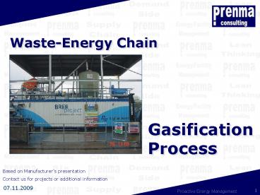
Gasification Process
Description:
1- After centrifuge sludge enters into the dryer at 20-25% ds ... (I) Produces Hot Uncleaned Combusted Gas to Pass Through Heat Recovery System. ... – PowerPoint PPT presentation
Number of Views:79
Avg rating:3.0/5.0
Title: Gasification Process
1
Gasification Process
Waste-Energy Chain
Based on Manufacturers presentation Contact us
for projects or additional information
2
Drying and GasificationA Complete Emission Free
Solution
Closed circuit Effluent Treatment system
under development
Downdraft Gasifier
Gas Engine and Generator
Drying
Briquetter
Producer Gas Scrubber
Booster fan
2
1
10
9
11
8
9
5
3
7
4
6
1- After centrifuge sludge enters into the dryer
at 20-25 ds 2- Clean dust free exhaust gases
after scrubber 3- Air enters the gasifier at
about stoichiometric levels 4- White ash (low
carbon) with leachable metals but when used as
road aggregate, produce zero leacheate.
5- Hot producer gas at 400oC exits the reduction
zone in the gasifier and enters the scrubber
where it is quenched to 50oC thereby removing
dust, acid gases, tars and also eliminate dioxin
reformation. 6- Scrubber residue - Tars, dust 7-
Make up water
8- Clean producer gas mainly consisting of H2,
CO, CH4, CO2, H2O, N2, to duel fuel compression
engine 9- Clean gas to dryer or invisible flare
3
Drying and GasificationA Complete Emission Free
Solution
- Key Features of WTE process
- Self sustainable
- Ability to treat all types of wastes
- Process is designed to meet all current and
expected legislative requirements, including 2004
Waste Incineration Directive. - No moving and ceramics parts. Novel air
distribution mechanism and World-wide process
patents. - Meets the proximity principle requirements.
- Currently developing zero effluent process using
polymers to remove metal ions, tars and oils from
scrubber effluent. - Low CAPEX and OPEX
4
- Flexibility
- (DG) Produces Clean, Medium Heating Value Fuel
Gas for Use in a Variety of Heat Engine Systems. - (I) Produces Hot Uncleaned Combusted Gas to Pass
Through Heat Recovery System.
5
CONCLUSIONS AND WAY FORWARD
- Produces Electricity from a Renewable Resource
- Reduces CO2 Emission Thereby Saving fossil fuels
- Long Term Waste Disposal Outlet Enables the
Producer Become Master of Its Own Destiny with No
Transport and Landfill Costs - Offers Significant Benefit for the Water and
Other Associated Industries
6
Newcastle University Pilot Scale Downdraft
Gasifier
1.60m
7
Reaction zones in a downdraft gasifier
Biomass
Drying Zone
The heat generated is used to drive the drying
and pyrolysis of the fuel and the gasification
reactions.
Gases to gas
burner or engine
Pyrolysis Zone
and generator
Oxidation Zone
Lighting port
Reduction
Pre-heated
Zone
primary air inlet
Ash pit
8
Gasification reactions
9
Effluent Treatment Using Micro Cellular Polymers
- Useful features
- Removes tars, oils and metal ions
- Longer life than conventional clay based
absorbers - Rapid reacting capability
- No harmful wastage
10
Anglian Water250 kWe Sludge Drying
Gasification System
11
Gasifier Inside the Container
12
Automatic Remote Control System MMI Screen
with SCADA Link
13
SKID-MOUNTED
14
Gas Burning Inside the Enclosed Flare Clean
Emission Free Low CV Gas
Typical gas characteristics H2 - 8-12 CO -
12-18 CH4 - 3-6 CO2 - 10-12 N2 - 45-55 H2O -
2-5 CV - 4.5-5.5kJ/kg
15
Don't hesitate to contact us
Thank you
prenma consulting Proactive Energy Management SPRL
for
Clos Joseph Hanse, 10 1170 Brussels Belgium
your
More concept details are available by opening
our webpage at the index INFO Click on the
picture to open !
kind
32 2 675 66 89
32 2 675 91 36
attention
Info_at_pr-en-ma.com
www.pr-en-ma.com


