
Cosmos%20Motion%20User%20Interface - PowerPoint PPT Presentation
Title:
Cosmos%20Motion%20User%20Interface
Description:
Cosmos Motion User Interface. Motion Browser. Pull Down Menu. Motion Toolbar. Cosmos Motion User Interface: Browser. Motion Parts ... – PowerPoint PPT presentation
Number of Views:126
Avg rating:3.0/5.0
Title: Cosmos%20Motion%20User%20Interface
1
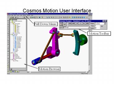
Cosmos Motion User Interface
Pull Down Menu
Motion Toolbar
Motion Browser
2
Cosmos Motion User Interface Browser
Motion Parts
Specify moving and stationary parts, and define
other motion entities directly from the
part. Override mass properties and define
initial conditions for parts
3
Cosmos Motion User Interface Browser
Motion Joints
4
Cosmos Motion User Interface Browser
Motion Forces
5
Cosmos Motion User Interface Browser
6
Cosmos Motion Pull Down Menu
7
Options Dialog - World
Set Force and Time Units for results
Specify gravity or click on world icon to reset
to earth gravity
Quickly specify gravity direction in global
coordinate frame
8
Options Dialog - Display
Control Visibility of Motion Symbols in
SolidWorks Graphics Window
Define Symbol Color for Motion Entity selected
Assign current Color and Size settings to ALL
Motion Entity types
Define Symbol Size for specific Motion Entities
Apply changes in Size or color to entities that
have already been defined (vs changes only
effecting newly defined entities)
9
Options Dialog - Simulation
Specify duration or time step intervals to
control length and number of results obtained
from the simulation
Enable/Disable animation while solving
If mass properties have already been calculated,
use them for next simulation
Solver Settings Should not need to alter these
for simple models. Generally only modify time
step limits and accuracy
10
Options Dialog
Animation Replay Settings for controlling replay
speeds and time range
By default, motion symbols are hidden when
animated
Specify a user defined replay time for VRML
animation (ie a time it will take to replay the
animation in a VRML player)
11
Basic Joint Types
Revolute Cylindrical
Translational Spherical
Universal Planar
Fixed In Line
In Plane Parallel Screw
Perpendicular Orientation
Orientation Planer
Origin
X reference axis
Axis of thread
1st Axis
2nd Axis
12
Constraint Mapping
What is constraint mapping? The automatic
transfer of assembly constraints to mechanical
joints Intelligence has been implemented to
minimize the mechanical joints formed between two
specific parts. Basic constraint types are merged
to simplified mechanical joints e.g. 1
coincident joints becomes a planar joint
2 orthogonal coincident joints becomes a
translational joint 3 orthogonal
coincident joints becomes a fixed joint 1
Coincident and 1 orthogonal concentric becomes a
revolute joint All assembly
constraints are mapped to joints including the
surface to surface constraints (eg, tangent
cylinder/plane tangent cylinder/cylinder). These
are known as compound joints
13
Mapped Constraints
Note There are 67 different ways of constraining
parts in SolidWorks
14
(No Transcript)
15
Redundancies
Occurs when one or more overall degrees of
freedom of a part are constrained by more than
one joint (duplicate constraints) Predominantly
the rotational degrees of freedom produce the
main areas of redundancies for moving
systems. To run a simulation, you cannot have
redundant constraints The joints have to be
chosen so that only one joint on the part defines
a specific degree of freedom. Solver has a built
in redundant constraint remover, but you must be
careful as it can remove the wrong constraint
with a large number of redundancies.
Recommended
CrystalGraphics Presentations


