
Conservation of energy: - PowerPoint PPT Presentation
1 / 17
Title:
Conservation of energy:
Description:
Air is heated in a heat exchanger by hot water. The water enters the heat exchanger at 45oC and experiences a 20oC drop in temperature. ... – PowerPoint PPT presentation
Number of Views:49
Avg rating:3.0/5.0
Title: Conservation of energy:
1
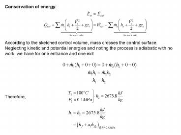
Conservation of energy
According to the sketched control volume, mass
crosses the control surface. Neglecting kinetic
and potential energies and noting the process is
adiabatic with no work, we have for one entrance
and one exit
Therefore,
2
5- Mixing chambers
The mixing of two fluids occurs frequently in
engineering applications. The section where the
mixing process takes place is called a mixing
chamber. The ordinary shower is an example of a
mixing chamber.
Solve Ex. 4.14, 4th Ed
3
Example 4-5 Steam at 0.2 MPa, 300oC, enters a
mixing chamber and is mixed with cold water at
20oC, 0.2 MPa, to produce 20 kg/s of saturated
liquid water at 0.2 MPa. What are the required
steam and cold water flow rates?
Control Volume The mixing chamber Property
Relation Steam tables Process Assume
steady-flow, adiabatic mixing, with no
work Conservation Principles Conservation of
mass
4
Conservation of energy
According to the sketched control volume, mass
crosses the control surface. Neglecting kinetic
and potential energies and noting the process is
adiabatic with no work, we have for two entrances
and one exit
Now, we use the steam tables to find the
enthalpies
5
(No Transcript)
6
6- Heat exchangers
Heat exchangers are normally well-insulated
devices that allow energy exchange between hot
and cold fluids without mixing the fluids. The
pumps, fans, and blowers causing the fluids to
flow across the control surface are normally
located outside the control surface.
Solve Ex. 4.15, 4th Ed
7
Example 4-6 Air is heated in a heat exchanger by
hot water. The water enters the heat exchanger
at 45oC and experiences a 20oC drop in
temperature. As the air passes through the heat
exchanger, its temperature is increased by 25oC.
Determine the ratio of mass flow rate of the air
to mass flow rate of the water.
Control Volume The heat exchanger Property
Relation Air ideal gas relations
Water steam tables or
incompressible liquid results Process Assume
adiabatic, steady-flow
8
Conservation Principles Conservation of mass
For two entrances, two exits, the conservation of
mass becomes
For two fluid streams that exchange energy but do
not mix, it is better to conserve the mass for
the fluid streams separately.
Conservation of energy According to the
sketched control volume, mass crosses the control
surface, but no work or heat transfer crosses the
control surface. Neglecting the kinetic and
potential energies, we have for steady-flow
9
We assume that the air has constant specific
heats at 300 K, Table A-2(a) (we don't know the
actual temperatures, just the temperature
difference). Because we know the initial and
final temperatures for the water, we can use
either the incompressible fluid result or the
steam tables for its properties.
Using the incompressible fluid approach for the
water, Table A-3, Cp, w 4.18 kJ/kg?K.
10
- A second solution to this problem is obtained
by determining the heat transfer rate from the
hot water and noting that this is the heat
transfer rate to the air. - Considering each fluid separately for
steady-flow, one entrance, and one exit, and
neglecting the kinetic and potential energies,
the first law, or conservation of energy,
equations become
11
7- Pipe and duct flow
- The flow of fluids through pipes and ducts is
often a steady-state, steady-flow process. - We normally neglect the kinetic and potential
energies however, depending on the flow
situation, the work and heat transfer may or may
not be zero.
Example 5-10 In a simple steam power plant, steam
leaves a boiler at 3 MPa, 600oC, and enters a
turbine at 2 MPa, 500oC. Determine the in-line
heat transfer from the steam per kilogram mass
flowing in the pipe between the boiler and the
turbine.
Control Volume Pipe section in which the heat
loss occurs. Property Relation Steam tables
Process Steady-flow Conservation Principles
12
Conservation of mass
For one entrance, one exit, the conservation of
mass becomes
Conservation of energy According to the
sketched control volume, heat transfer and mass
cross the control surface, but no work crosses
the control surface. Neglecting the kinetic and
potential energies, we have for steady-flow
We determine the heat transfer rate per unit mass
of flowing steam as
13
We use the steam tables to determine the
enthalpies at the two states as
Example 4-7 Air at 100oC, 0.15 MPa, 40 m/s, flows
through a converging duct with a mass flow rate
of 0.2 kg/s. The air leaves the duct at 0.1 MPa,
113.6 m/s. The exit-to-inlet duct area ratio is
0.5. Find the required rate of heat transfer to
the air when no work is done by the air.
14
Control Volume The converging duct Property
Relation Assume air is an ideal gas and use
ideal gas relations Process Steady-flow Conserv
ation Principles Conservation of mass
For one entrance, one exit, the conservation of
mass becomes
15
Conservation of energy According to the
sketched control volume, heat transfer and mass
cross the control surface, but no work crosses
the control surface. Here keep the kinetic
energy and still neglect the potential energies,
we have for steady-state, steady-flow process
In the first law equation, the following are
known P1, T1 (and h1), , , , and
A2/A1. The unknowns are , and h2 (or T2).
We use the first law and the conservation of mass
equation to solve for the two unknowns.
16
Solving for T2
Assuming Cp constant, h2 - h1 Cp(T2 - T1)
17
Looks like we made the wrong assumption for the
direction of the heat transfer. The heat is
really leaving the flow duct. (What type of
device is this anyway?)
8- Liquid pumps
The work required when pumping an incompressible
liquid in an adiabatic steady-state, steady-flow
process is given by
The enthalpy difference can be written as