
CIEMAT ACTIVITIES ON STRIPLINE KICKERS - PowerPoint PPT Presentation
1 / 14
Title:
CIEMAT ACTIVITIES ON STRIPLINE KICKERS
Description:
Kicker location in CTF3 Combiner Ring (CR) Extraction of beam after 4 ... Excellent leak test. Good vacuum. Mild bake-out required. High voltage pulser test. ... – PowerPoint PPT presentation
Number of Views:39
Avg rating:3.0/5.0
Title: CIEMAT ACTIVITIES ON STRIPLINE KICKERS
1
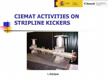
CIEMAT ACTIVITIES ON STRIPLINE KICKERS
I. Rodríguez
2
Outline
- CTF3 Combiner Ring Kicker
- CTF3 TL2 Tail Clippers
- Stripline kickers in ILC
- Conclusions
2
3
CTF3 Combiner Ring Kicker (1)
- Kicker location in CTF3 Combiner Ring (CR)
KICKER
- Extraction of beam after 4-turns combination in
the CR - Substitution of an old magnetic kicker to improve
beam impedance
3
4
CTF3 Combiner Ring Kicker (2)
- Specifications to meet
- 1 homogeneity is the most challenging
specification
4
5
CTF3 Combiner Ring Kicker (3)
- Design and calculations
- Several cross sections considered. Planar
electrodes chosen - 3D model in HFSS 1.7 m electrodes.
- Good transmission of pulse frequency content
- Wakefields studied using CST Particle Studio at
CIEMAT and GDFidl at CERN
- Aperture 41 mm
- Electrode height 44 mm
- Tube radius 54 mm
- Border angle 42º
- Border length 8.2 mm
- Electrode width 2 mm
- Z0 49.99 O
- Homogeneity 0.74
S112lt0.03 (0 to 50 MHz)
5
6
CTF3 Combiner Ring Kicker (4)
- Manufacturing Fully in stainless-steel
- Many high vacuum welds required
- Challenging stand-off support
- Special beam pipe transitions
6
7
CTF3 Combiner Ring Kicker (5)
- Testing
- Vacuum test and leak rate successful. Mild bake
out required - High voltage pulser test 16 kV, 5 ns, 50 Ohm
load - DC high voltage test 18 kV successfully tested
(14 kV nominal) - RF tests
Almost no reflection lt 0.2 in power up to 35
MHz
7
8
CTF3 TL2 Tail Clippers (1)
- Tail Clippers location in CTF3
TAIL CLIPPERS
- Shorten the bunch trains for conditioning before
PETS - Extremely fast response required to precisely cut
the beam between bunches
8
9
CTF3 TL2 Tail Clippers (2)
- Specifications to meet
- High frequency transmission is the most
challenging specification
9
10
CTF3 TL2 Tail Clippers (3)
- Design and calculations
- Several cross sections considered
- Smooth coax to stripline transitions for enhanced
RF transmission - Excellent high frequency transmission up to 2 GHz
Homog19Ø 66 mm
Homog15Ø 71 mm
Homog10Ø 78 mm
10
11
CTF3 TL2 Tail Clippers (4)
- Manufacturing
- Stainless steel tube and aluminium electrodes
- Electrodes fully manufactured using CNC
- High voltage 50 Ohm feedthroughs
- Challenging coax to stripline connections
11
12
CTF3 TL2 Tail Clippers (5)
- Testing
- Excellent leak test. Good vacuum. Mild bake-out
required - High voltage pulser test. Excellent behaviour at
high freqs - DC high voltage test 3 kV successfully tested (2
kV nominal) - RF tests
12
13
ILC stripline kickers
- Many stripline kickers in different zones DRs,
RTML, etc - Most challenging ones Damping Ring injection and
extraction kickers. DRs 6.7 km, 5 GeV. - The electrical pulser requirements are extremely
challenging.
ILC Reference Design Report (August, 2007)
13
14
Conclusions
- Two stripline kickers have been fully designed,
manufactured and tested. Tail Clipper power
supplies were designed at CERN. - ILC kickers are very similar except from the
pulsed power supply.
14