
MULTIMETER - PowerPoint PPT Presentation
1 / 17
Title:
MULTIMETER
Description:
A moving-coil galvanometer withb. Some shunt resistors (in parallel) Current. G. G. G. ... Galvanometer. Switch. R1. R2. G. Resistance can be. determined in ... – PowerPoint PPT presentation
Number of Views:2692
Avg rating:5.0/5.0
Title: MULTIMETER
1
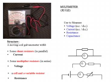
MULTIMETER (???)
- Use to Measure
- Voltage (a.c. / d.c.)
- Current (a.c. / d.c.)
- Resistance
- Capacitance
Structure A moving-coil galvanometer withb
- Some shunt resistors (in parallel)
- Current
- . Some multiplier resistors (in series)
- Voltage
- a cell and a variable resistor
- Resistance
2
Galvanometer
Switch
3
Galvanometer
Switch
4
Galvanometer
Switch
5
Galvanometer
Switch
2.5 mA passing through gives f.s.d.
6
Galvanometer
Switch
50 mA passing through gives f.s.d.
7
Galvanometer
G
R2
R1
Switch
-
0.1 V across it gives f.s.d.
8
Galvanometer
R3
G
R2
R1
-
2.5 V across it gives f.s.d.
Switch
9
Galvanometer
R4
R3
G
R2
R1
-
10 V across it gives f.s.d.
Switch
10
Galvanometer
G
R1
R2
-
Switch
Resistance can be determined in this circuit.
11
The Figure shows part of the internal structure
of a typical multimeter. The resistance of R1,
R2 and R3 are 9.8 kW, 200W and 48kW respectively.
A rotary switch S enables the various full-scale
values of current or voltage to be chosen.
(I) Calculate the resistance of the coil and the
current flowing through it for full-scale
deflection. Show your working.
(II) Calculate the resistance of R4.
(III) In the space provided in the figure, add
two components to the circuit so that the
multimeter can be used to measure resistance
between its input terminals when switch S is set
at X. Describe briefly how to adjust for zero
ohm position.
12
(I) Calculate the resistance of the coil and the
current flowing through it for full-scale
deflection. Show your working.
Consider the switch set at 50mA / 0.1V, In the
condition of f.s.d. of the meter, the current
passes through it is 50mA and the voltage
across it is 0.1V.
By Ohms law at the internal resistance r, (0.1)
(50 x 10-6) r
13
(I) Calculate the resistance of the coil and the
current flowing through it for full-scale
deflection. Show your working.
r
G
50mA
R1
R2
-
0.1V
Consider the switch set at 50mA / 0.1V, In the
condition of f.s.d. of the meter, the current
passes through it is 50mA and the voltage
across it is 0.1V.
By Ohms law at the TOTAL resistance of the
ammeter, (0.1) (50 x 10-6) ((9800 200)-1
r -1)-1 r 2500 W Io 0.1 /
2500 4.0 x 10⁻⁵ A
14
(II) Calculate the resistance of R4.
0.1V
r
R4
50mA
R3
G
R1
R2
-
10V
Consider the switch set at 10V, In the
condition of f.s.d. of the meter, the current
passes through it is 50mA and the voltage
across it is 10V.
By Ohms law at the TOTAL resistance of the
ammeter, (10) (50 x 10-6) (R4 48000) 0.1
R4 150000 W
15
(III) In the space provided in the figure, add
two components to the circuit so that the
multimeter can be used to measure resistance
between its input terminals when switch S is set
at X. Describe briefly how to adjust for zero
ohm position.
A cell with positive connected to the X and a
variable resistor are connected.
In order to adjust for zero ohm position, the
variable resistor is altered.
16
(No Transcript)
17
Techniques of using Multimeter
1. Choose a correct range for measurement (V,
I, R) (large f.s.d. and low sensitivity
first)
2. Set zero for the measurement V
and I (set one then apply to all ranges)
R (set zero for each range)
3. Connect the multimeter correctly to the
circuit.
4. Take readings on a correct scale
18
Zero-setting for resistance
back
Zero-setting for voltage and current
19
(No Transcript)
20
(No Transcript)
21
(No Transcript)
22
back
23
(No Transcript)
Recommended
CrystalGraphics Presentations


