
Chapter 8 Polarization - PowerPoint PPT Presentation
1 / 25
Title:
Chapter 8 Polarization
Description:
Superposition of two waves whose E-fields are mutually ... Application of Fresnel equations: The reflectance of nature light: Degree of ... Fresnel's ... – PowerPoint PPT presentation
Number of Views:215
Avg rating:3.0/5.0
Title: Chapter 8 Polarization
1
- Chapter 8 Polarization
- December 1, 3 Nature of polarization
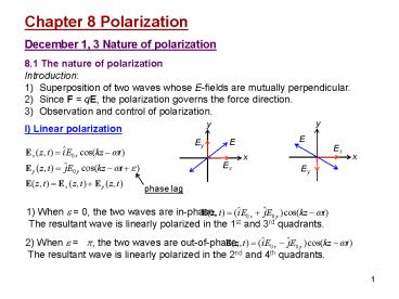
- 8.1 The nature of polarization
- Introduction
- Superposition of two waves whose E-fields are
mutually perpendicular. - Since F qE, the polarization governs the force
direction. - Observation and control of polarization.
- I) Linear polarization
phase lag
1) When e 0, the two waves are in-phase, The
resultant wave is linearly polarized in the 1st
and 3rd quadrants.
2) When e p, the two waves are out-of-phase,
The resultant wave is linearly polarized in the
2nd and 4th quadrants.
2
y
II) Circular polarization
1) When E0xE0yE0, e -p /2 , a kz-wt,
the resultant wave is right-circularly polarized
(rotate clockwise).
- 2) When E0xE0xE0, e p /2 ,
- a -kz wt, the resultant wave is
left-circularly polarized (rotate
counterclockwise). - Circular light
- The amplitude E0 does not change.
- The direction of E rotates.
- The end point of E traces out a circle.
- A linearly polarized wave can be synthesized from
two oppositely polarized circular waves of equal
amplitude. (Example)
3
- III) Elliptical polarization
- Elliptical light The E vector rotates and
changes its magnitude as well. The end point of E
traces out an ellipse.
Let us remove kz-wt and see what is the relation
between Ex and Ey
This is an ellipse tilting at an angle a given
by When e p /2, we have When e 0, p,
we have
4
Example
- State of polarization
- Right-circular light R-state
- Left-circular light L-state
- Linearly polarized light P-state, superposition
of R- and S-states with equal amplitude. - Elliptically polarized light E-state,
superposition of R- and S-states with different
amplitudes.
5
Nature light Each atom emits a polarized wave
train of 10-8s. The wave trains are random in
polarization. As a result, nature light is
unpolarized, or randomly polarized.
8.1.5 Angular momentum and the photon
picture Circularly polarized light sets a charge
into circular motion. E-field exerts torque to
the charge (with the
same frequency as light)
Newtons second law for rotation
(L is the angular momentum of the
charge) Power generated by a torque Direction
of L -k for R-state, k for L-state (right-hand
rule). When a circularly polarized photon is
absorbed, it transfers an angular momentum
The intrinsic angular momentum (spin) of a
photon is .
6
Read Ch8 1 Homework Ch8 (1-6) 2,3,5 Due
December 12
7
Proof of Eq. 8.15 What is the tilting angle a
of the ellipse
Solution One method is from Eqs. 8.11 and
8.12, finding the optimum angle qm that makes
the largest. Pluck this qm into Eqs. 8.11 and
8.12, we get the Ex and Ey for tana. Let us try
an easier way. The problem is at the condition
of Eq. 8.14, what is the maximum ?
This can be solved by the method of Lagrange
multiplier.
8
From the last two equations, we have
Let , we have
9
- December 5 Birefringence
- 8.2 Polarizers
- Polarizer An optics whose input is nature light
and whose output is some forms of polarized
light. Example linear polarizer. - Physical mechanisms for polarizers
- Dichroism (selective absorption)
- Reflection
- Scattering
- Birefringence (double refraction)
- Polarizer and analyzer, transmission axis,
extinction axis - Maluss law transmitted intensity
8.3 Dichroism Dichroism Selective absorption of
one of the two orthogonal P-state
light. Wire-grid polarizer The transmission
axis of the grid is perpendicular to the wires.
10
Dichroic crystals (example tourmaline) The
E-field perpendicular to the optic axis is
strongly absorbed. Polaroid dichroic sheet
polarizer.
8.4 Birefringence Anisotropy of binding force of
an electron cloud causes the anisotropy in the
refractive indexes for different
polarizations. 8.4.1 Calcite (CaCO3) Cleavage
plane a surface ready to cut. Cleavage form a
sample of which each surface is a cleavage
plane. Optic axis (here 3-fold symmetry) the
refractive index depends on whether the E-field
is parallel or perpendicular to the optic axis.
Principle plane a plane contains the optic
axis. Principle section a principle plane normal
to a pair of cleavage planes. A beam passing
through a principle section o-ray E-field
normal to the principle section. e-ray E-field
parallel to the principle section.
11
Principle Light whose polarization is parallel
to the optic axis feels a refractive index of ne
and propagates with a speed of v//. Light whose
polarization is perpendicular to the optic axis
feels a refractive index of no and propagates
with a speed of v-. Huygenss explanation 1)
o-ray, wavelets expand with v-. 2) e-ray, E-field
component parallel to the optic axis
propagates with v// (gt v-). E-field component
perpendicular to the optic axis propagates with
v-. This results in elliptical wavelets.
Ray direction from the origin of each wavelet
to its tangent point with the planar
envelope.
8.4.2 Birefringent crystals Optic axis a
direction about which the atoms are arranged
symmetrically. Cubic, uniaxial, biaxial
crystals. Negative (neltno) and positive (negtno)
uniaxial birefringent crystals.
12
Wavelets in uniaxial crystals
Positive uniaxial crystal
Negative uniaxial crystal
8.4.3 Birefringent polarizers Example
Glan-Foucault (Glen-Air) polarizer. Calcite,
no1.6584, ne1.4864 qc(o-ray) 37.08º,
qc(e-ray) 42.28º.
13
Read Ch8 2-6 Homework Ch8 (7-26)
12,18,21(Optional),24 Due December 12
14
December 8 Scattering and polarization
- 8.5 Scattering and polarization
- Polarization by scattering
- If the incident light is unpolarized, then
- The scattered light in the forward direction is
unpolarized. - The scattered light at 90º is linearly polarized.
- The scattered light in other directions are
partially polarized.
The polarization of the scattered light from a
linear dipole is along the longitude line.
8.6 Polarization by reflection Brewster angle
(polarization angle) For an unpolarized incident
light, at the Brewster angle, only the component
with E-field normal to the incidence plane can
be reflected.
15
Application of Fresnel equations The reflectance
of nature light
Degree of polarization Here Ip and In are
the constituent flux densities of the incident
light. If an analyzer is used, then
16
Read Ch8 2-6 Homework Ch8 (27-36) 31,32,33,34
Due December 17
17
December 10 Retarders 8.7 Retarders Retarder An
optics that changes the polarization of the
incident wave. Principle of retarders One
constituent P-state is phase-retarded with
respect to the other. 8.7.1 Wave plates and
rhombs The optic axis is parallel to the surfaces
of the plate. Relative phase difference
(retardance) between the emerging e-and o-waves
Fast axis The axis along which a light polarized
will propagate faster. For nelt no, the optic axis
is the fast axis. Half-wave plate
Linear input Rotate light initially polarized at
angle q by an angle of 2q. Elliptical input
flip the tilting angle, invert the handedness.
18
Quarter-wave plate
Linear input Covert into elliptical
light. Linear input at 45º Covert into circular
light.
General considerations
- Zero-order wave plate m 0.
- Example
- Quartz at 550 nm, ne-no0.0092, d 15 mm for
QWP, and d 30 mm for HWP. - Multiple-order wave plate
- Less expensive, but sensitive to wavelength,
incident angle and temperature. - Compound zero-order wave plate
- Eliminates the bandwidth and temperature
effects.
8.7.2 Compensators and variable
retarders Compensator an optics that produces
controllable retardance. Babinet compensator
19
Read Ch8 7 Homework Ch8 (37-49)
37,41,42,45,46 Due December 17
20
Achromatic wave plates
Estimation of l1 and l2 (e.g., QWP) In the
wavelength range considered, the phase
retardation should be as close as possible to p/2
(minimum rms).
? l1603 mm, l2477 mm
Discussion Why do we need two materials?
For normal compound zero-order wave plates (one
material), l1-l2 is fixed, thus
is fixed. For achromatic wave plates (two
materials), l1 and l2 can be chosen to minimize
, which greatly expands the
bandwidth.
21
December 12 Optical activity and induced optical
effects 8.10 Optical activity Optical activity
(optical rotation) The polarization plane of a
linearly polarized light is rotated when
traveling through certain materials. It occurs in
solutions of chiral molecules (a molecule not
superimposable on its mirror image), and solids
with rotated crystal planes. E.g., corn
syrup. Dextrorotatory (d-rotatory) materials and
levorotatory (l-rotatory) materials. Fresnels
explanation (1825) Circular birefringence
R-state and L-state have different propagation
speeds. Incidence In the medium
Rotation direction kR gt kL, counterclockwise,
l-rotatory kR lt kL, clockwise,
d-rotatory. Angle of rotation (traditional) Spe
cific rotation , e.g,
30º/inch for corn syrup.
22
8.11 Induced optical effects ? optical
modulators I) Photoelasticity (mechanical
birefringence, stress birefringence, Brewster
1816) Under compression or tension, the material
obtains the property of a uniaxial crystal. The
effective optical axis is in the direction of the
stress, and the induced birefringence is
proportional to the stress. II) Faraday effect
(Faraday 1845) The plane-of-vibration of a
linearly polarized light inside a medium is
rotated by a strong magnetic field in the light
propagation direction. Rotation angle V
Verdet constant, B magnetic field, d length
of the medium Sign convention Positive V (most
materials) ? l-rotatory when k//B, d-rotatary
when k//-B. No such reversal occurs in nature
optical activity.
Classic explanation P RL ? Circular light
drives circular orbits of electron ? B-field
introduces radial force whose direction depends
on R or L ? two polarization (nR and nL) for a
given B-field. Applications 1) Optical
modulator, 2) Faraday insulator (q 45º)
23
III) Kerr effect (Kerr 1875) An isotropic
substance becomes birefringent in an E-field. The
optical axis is in the direction of the E-field,
the birefringence
K Kerr constant (mostly positive).
? Quadratic electro-optic effect.
Retardation Half-wave voltage Example Nitrobe
nzene K 22010-7cm/statvolt2, Vl/230000 V.
Applications High-speed shutters, Q-switches.
Frequency 1010 Hz.
24
III) Pockels effect (Pockels 1893) An
electro-optic effect where the induced
birefringence is proportional to the E-field and
thus proportional to the applied voltage (second
order nonlinear effect). Exists only in crystals
that have no center of symmetry. Response time lt
10 ns, up to 25 GHz.
Pockels cell configurations transverse (E? optic
axis) and longitudinal (E // optic
axis) Example Longitudinal configuration
Retardation r63 Electro-optic constant (?
second-rank electro-optical tensor
rij) Half-wave voltage Example KDP
r6310.61012 V/m, Vl/27600 V (a factor of 5
less than Kerr cell).
25
Read Ch8 8-13 Homework Ch8 (50-72) 50,51,65
Due December 17
Recommended
CrystalGraphics Presentations


