
Altium’s PCB Designer Tools Guide - PowerPoint PPT Presentation
Title:
Altium’s PCB Designer Tools Guide
Description:
Altium Designer is considered the epitome of EDA tools for hardware design engineers when it comes to professional schematic and PCB design. It is inclusive and encompassing as far as all the steps in the design and management process are concerned. – PowerPoint PPT presentation
Number of Views:1
Title: Altium’s PCB Designer Tools Guide
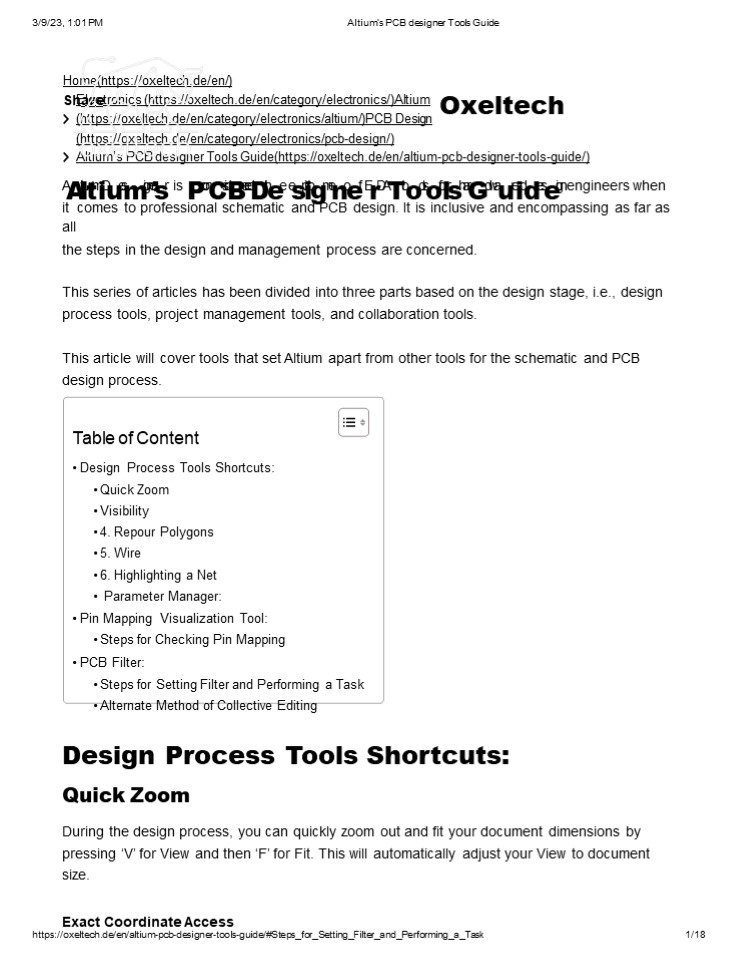
1
3/9/23, 101 PM
Altiums PCB designer Tools Guide
Home(https//oxeltech.de/en/) ShEalercetronics
(https//oxeltech.de/en/category/electronics/)Alti
um (https//oxeltech.de/en/category/electronics/a
ltium/)PCB Design (https//oxeltech.de/en/categor
y/electronics/pcb-design/)
Oxeltech
- Altiums PCB designer Tools Guide(https//oxeltech
.de/en/altium-pcb-designer-tools-guide/) - AAltilutmiDuesmignesr is PconCsidBeredDthee
espiitogmenoef ErDATtooolsofolrsharGdwaureiddeseig
n engineers when it comes to professional
schematic and PCB design. It is inclusive and
encompassing as far as all - the steps in the design and management process
are concerned. - This series of articles has been divided into
three parts based on the design stage, i.e.,
design process tools, project management tools,
and collaboration tools. - This article will cover tools that set Altium
apart from other tools for the schematic and PCB
design process. - Table of Content
- Design Process Tools Shortcuts
- Quick Zoom
- Visibility
- 4. Repour Polygons
- 5. Wire
- 6. Highlighting a Net
- Parameter Manager
- Pin Mapping Visualization Tool
- Steps for Checking Pin Mapping
2
3/9/23, 101 PM Altiums PCB designer Tools
Guide During part placement or polygon placement,
there is a requirement to have access to exact
coordinates for accuracy and aesthetics. This can
be done by pressing J for Jump and then L
for jumping to that location. A window will open
up for you to enter coordinates.
Oxeltech
Exact Coordinate Access in Altium Now when you
press Enter, your cursor will be at the entered
coordinates. Visibility During PCB design, you
often have to switch visibility to check your
placement routing with reference to other
layers. For this, you can use the ShiftS
command. Lets take an example to show how this
works. Here is a PCB cutout
Layout Visibility Across Different Layers in
Altium
3
3/9/23, 101 PM Altiums PCB designer Tools
Guide When you press ShiftS once, this View
changes to the following View in which the top is
highlighted and the layers underneath are in the
faded form Oxeltech
Layout Visibility Across Different Layer in
Altium Now, if you press ShiftS again, the
visibility shifts to the selected layer (top
layer in this case), and the rest are switched
off
4
3/9/23, 101 PM
Altiums PCB designer Tools Guide
Oxeltech
- Layout Visibility Across Different Layers in
Altium oxeltech - Repour Polygons
- During PCB design, we must shelve and re-pour
polygons and planes from time to time. To re-
pour all the polygons/planes, you can press T for
Tools, G for Polygon Pours, and then A for re-
pour All. - Wire
- To toggle the Wire tool for connecting devices in
Schematic or routing in PCB, the CtrlW shortcut
can be used. The cursor will change to Cross upon
using this shortcut. - Highlighting A Net
- Keep pressing Shift and hovering over the net in
question to highlight a net. The entire net can
now be seen clearly because it has been
highlighted for focus. - Parameter Manager
- Parameter Manager is a feature using which we can
add and modify parameters in the project.
Parameter Manager can be accessed in the
Schematic window by selecting the Tools tab and
clicking Parameter Manager
5
3/9/23, 101 PM
Altiums PCB designer Tools Guide
Oxeltech
Altium Parameter Manager We can edit individual
parameters and all the parameters based on their
category. Furthermore, new parameters can also
be added. To add a new parameter, you have to
click on the Add Column button, and the
following dialogue box opens up in which you add
the name, association, and value for that column
How to Add New Parameters in a Project in Altium
6
3/9/23, 101 PM
Altiums PCB designer Tools Guide
Oxeltech
- Pin Mapping Visualization Tool
- Reviewing the pin mapping for microcontrollers
and other ICs with multiple pins takes time to
quickly check the mapping of the schematic symbol
and the PCB footprint side by side. - Steps For Checking Pin Mapping
- Open the integrated library you created for the
project and the part you want to check. The
window that opens up shows both symbol and
footprint. - Now, if you click on any pin in the symbol, the
corresponding pin in the footprint will be
highlighted. In this way, you can verify the pin
connections using the datasheet.
How to Check Pin Mapping in Altium
7
3/9/23, 101 PM PCB Filter
Altiums PCB designer Tools Guide
During the PCB design process, there comes a
situation when you have to perform a task on
several objects of the same type all at once. In
this case, peOrfoxrmeingltthee scamhe task
separately on each object becomes quite tedious.
Altiums PCB Filter is a huge help in this
scenario. You can add filters on different object
types, such as designators or component types,
such as vias or nets, etc., and then perform
the intended task on them all at once. Steps For
Setting Filter And Performing A Task 1. Select
PCB Filter from the bottom left.
PCB Filter in Altium 2. You can add specific
filter commands in the Filter section. For
instance, we want to change the size of all
designators on the board. Well write
isdesignator expression in the section and
check the Select check box.
PCB Filters in Altium Youll see that all the
designators have been highlighted.
8
3/9/23, 101 PM
Altiums PCB designer Tools Guide
Oxeltech
- PCB Filter in Altium oxeltech
- Now you can go to the properties and change the
required parameter. Another example for these
types of tasks, is changing via size of all GND
vias. - Alternate Method Of Collective Editing
- You can perform the same collective action
through another method. - Now if you want to change designator size, you
can go to the String Type Object for designators
and change status from Any to Same. - Right-click on the object that needs to be
altered and click on Find Similar Objects.
Collective Editing in Altium The following
window should open up.
9
3/9/23, 101 PM
Altiums PCB designer Tools Guide
Oxeltech
Collective Editings in Altium Now when OK is
pressed, we can see that all the designators are
selected and we can go to Properties tab and
perform changes as we did in PCB Filter
method. For any Altium or PCB layout
(https//oxeltech.de/en/pcb-layout-assembly/)
related issues, Firmware Development
(https//oxeltech.de/en/firmware-development/),
or any Hardware Design related challenge in
general, feel free to Contact Us
(https//oxeltech.de/en/contact-us/) for our
consultancy. You can check out our other
Technical Blogs (https//oxeltech.de/en/blog/) on
various topics or visit our new website
Oxeltech.de (https//oxeltech.de/) to find all
about our services and products. Team
Oxeltech July 6, 2022(https//oxeltech.de/en/2022/
07/06/) 653 am
No
(https//oxeltech.de/en/altium-pcb-designer-tools-
Comment guide/respond) s
Did You Enjoy This Article?
10
3/9/23, 101 PM
Altiums PCB designer Tools Guide
Join Oxeltech community and get updated every
week We have a lot more just for you! Lets join
us now Oxeltech Email
Recent Post
Subscribe Now How To Write A Driver For
Accelerometer LIS3DSH In Zephyr?
(Https//Oxeltech.De/En/How-To-Write-A-Driver-For-
nsubscribe anytime
? No charge ? U Leave A Re
Accelerometer-Lis3dsh-In-Zephyr/) January 16, 2023
ply (https//oxeltech.de/en/how- Ytoo-uwrrietem-a-
ildaridvder-fsosr-will not be published. Required
fields are marked accelerometer-lis3dsh-
Cino-zmempheynrt/) SoC Vs SoM System On Chip
Vs System On Module (Https//Oxeltech.De/En/Syste
m-On-Chip-Soc-Vs-System-On- Module-Som/) December
23, 2022
(https//oxeltech.de/en/system-
on-chip-soc-vs-system-
on-module-som/)
Name
ESD Best Practices (Https//Oxeltech.De/En/Esd-Bes
t- Practices/) December 6, 2022
W(htetpbsit/e/oxeltech.de/en/esd-
best-practices/)
11
Altiums PCB designer Tools Guide anHdowwebTsoitCe
hinotohsise bBroewtwseeer nfoMr tihceronceoxnt
ttrimoleleIrcAonmdmFePnGt. A For Your Embedded
Application? (Https//Oxeltech.De/En/Fpga-Vs-
Microcontroller/)
3/9/23, 101 PM
Save my name, email, Post Comment
Oxeltech
December 6, 2022
(https//oxeltech.de/en/fpga- vs-microcontroller/
) Hold-Up Capacitor Calculations And Uses
(Https//Oxeltech.De/En/Hold-Up-Capacitor-Calculat
ions-And- Use/) November 6, 2022
(https//oxeltech.de/en/hold- up-capacitor- calcu
lations-and-use/) MTBF Concept And Application
(Https//Oxeltech.De/En/Mtbf- Concept-And-Applica
tion/) October 6, 2022
(https//oxeltech.de/en/mtbf- concept-and- applic
ation/) All About LiDAR Technology Complete
Guide (Https//Oxeltech.De/En/Lidar-Technology/)
September 6, 2022
(https//oxeltech.de/en/lidar- technology/)
12
Altiums PCB designer Tools Guide How To Choose
The Right Flash Memory For Your Embedded
Application. (Https//Oxeltech.De/En/Flash-Memory-
In- Embedded-System/)
3/9/23, 101 PM
Oxeltech
August 6, 2022
(https//oxeltech.de/en/flash-
memory-in-embedded- system/) Altiums PCB
Designer Tools Guide (Https//Oxeltech.De/En/Alti
um-Pcb-Designer-Tools-Guide/) July 6, 2022
(https//oxeltech.de/en/altium-
pcb-designer-tools- guide/) Altiums Amazing
Features Project Management Tools
(Https//Oxeltech.De/En/Altium-Project-Management/
) June 6, 2022
(https//oxeltech.de/en/altium-
project-management/) Ceramic Capacitors Which
Aspects To Consider When Using Them In Your
Design? (Https//Oxeltech.De/En/Ceramic- Capacitor
-Uses/) May 8, 2022
(https//oxeltech.de/en/ceramic- capacitor-uses/)
13
Altiums PCB designer Tools Guide How To Control
DC Servo Motors? (Https//Oxeltech.De/En/Dc-
Servo-Motor-Controller/)
3/9/23, 101 PM
April 21, 2022
Oxeltech
(https//oxeltech.de/en/dc- servo-motor-controlle
r/) Your Ultimate Guide To Designing Analog
Filters (Https//Oxeltech.De/En/Analog-Filters-De
sign-Guide/) April 9, 2022
(https//oxeltech.de/en/analog-
filters-design-guide/) Consumer Electronics,
Industrial Electronics And Industrial Standards
(Https//Oxeltech.De/En/Consumer-And-Industrial-
Electronics-Standards/) April 1, 2022
(https//oxeltech.de/en/consumer-
and-industrial- electronics-standards/) Design
Guide On USB-C PD Charge-Through Feature With
Data Role Swap (Https//Oxeltech.De/En/Usb-C-Desi
gn-Guide/) March 23, 2022
(https//oxeltech.de/en/usb- c-design-guide/) ium
s Team Collaboration Features In PCB Design
tps//Oxeltech.De/En/Altium-365-Team-Collaboration
/)
Alt (Ht
14
3/9/23, 101 PM
Altiums PCB designer Tools Guide
rch 6, 2022
(https//oxeltech.de/en/altium-Ma 365-team-collabo
ration/)
Oxeltech
Using Zephyr OS For Interfacing An IMU Sensor
With NRF52 Over SPI (Https//Oxeltech.De/En/Using
-Zephyr-Os-For- Interfacing-An-Imu-Sensor-With-Nr
f52-Over-Spi/) July 25, 2021
(https//oxeltech.de/en/using-
zephyr-os-for- interfacing-an-imu-
sensor-with-nrf52-over- spi/) Use Of Grounding
Techniques In PCB Design To Prevent
Electromagnetic Interference (EMI)
(Https//Oxeltech.De/En/Pcb-Grounding-Techniques/)
June 29, 2021
(https//oxeltech.de/en/pcb- grounding-techniques
/) PCB Design Guidelines For Reduced
Electromagnetic Interference (EMI)
(Https//Oxeltech.De/En/Pcb-Design-
Guidelines-For-Reduced-Electromagnetic-Interferenc
e-Emi/) May 5, 2021
(https//oxeltech.de/en/pcb- design-guidelines-fo
r- reduced- electromagnetic- interference-emi/)
15
Altiums PCB designer Tools Guide EMC Vs EMI
Compatibility, Principles Mechanism
Comparisons (Https//Oxeltech.De/En/Emc-And-Emi/)
3/9/23, 101 PM
April 18, 2021
Oxeltech
(https//oxeltech.de/en/emc- and-emi/)
Continue Reading
(https//oxeltech.de/en/how-to-write-a-driver-for-
accelerometer-lis3dsh-in-zephyr/) How To Write A
Driver For Accelerometer LIS3DSH In Zephyr?
(Https//Oxeltech.De/En/How-To-Write-A-Driver-For-
Accelerometer-Lis3dsh-In- Zephyr/) Team Oxeltech
January 16, 2023 In our previous Zephyr blog,
we looked at how to interface a simple IMU
Accelerometer sensor with Zephyr RTOS running on
NRF52832. Knowing how
16
3/9/23, 101 PM Altiums PCB designer Tools
Guide Read More (Https//Oxeltech.De/En/How-To-Wri
te-A-Driver-For-Accelerometer-Lis3dsh-In-
Zephyr/)
Oxeltech
(https//oxeltech.de/en/system-on-chip-soc-vs-syst
em-on-module-som/) SoC Vs SoM System On Chip
Vs System On Module (Https//Oxeltech.De/En/Syste
m-On-Chip-Soc-Vs-System-On-Module-Som/) Team
Oxeltech December 23, 2022 What is System on
Chip, SoC? A System on Chip or SoC is a key
component in Embedded Systems today. An SoC
refers to a Read More (Https//Oxeltech.De/En/Sys
tem-On-Chip-Soc-Vs-System-On-Module-Som/)
Would You Like Some Info?
Name Name Email
17
3/9/23, 101 PM
Altiums PCB designer Tools Guide
Message
Oxeltech
Message
Send
Let's Discuss Contact Us for any
Queries info_at_oxeltech.de (mailtoinfo_at_oxeltech.de
) (mailtoinfo_at_oxeltech.de)
49176 64738476 (Tel4917664738476)
(https
(tel4917664738476)
//ww
w.link
edin.c om/c ompa ny/ox eltech /)
Hardware Design Simulation(https//oxeltech.de/e
n/hardware-design-simulation/)
PCB Layout Assembly(https//oxeltech.de/en/pcb-l
ayout-assembly/) Firmware Development(https//oxel
tech.de/en/firmware-development/)
Imprint(https//oxeltech.de/en/imprint/) Contact
Us(https//oxeltech.de/en/contact-us/)
Blog(https//oxeltech.de/en/blog/) Member Of
IHK (Https//Www.Ihk.De/)
18
3/9/23, 101 PM
Altiums PCB designer Tools Guide
Oxeltech
Recommended
CrystalGraphics Presentations


