
Project Sagarmala - PowerPoint PPT Presentation
Title:
Project Sagarmala
Description:
Shipping and Vessels Project Electrical and Controls Systems – PowerPoint PPT presentation
Number of Views:1224
Title: Project Sagarmala
1
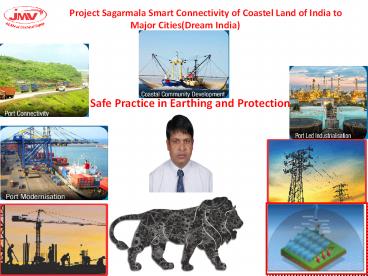
Project Sagarmala Smart
Connectivity of Coastel Land of India to Major
Cities(Dream India)
Safe Practice in Earthing and Protection
2
Sikhana to Padega Hi Follow NBC2016
3
Follow Safety in Electrical Instalation Shocks
4
Earthing Design and Require Result
- For substation Large Power below 1.00Ohm
- For substation Small Power below 2.00Ohm
- SCADA/TELECOM and AutomationFor substation
Large Power below 0.50Ohm - Tower and Other Structure between 8-15Ohm
- Lightning Surge Protection 50KA below 5Ohm or
100KA between 8-15Ohm - Follow Standard IEC /IEEE
- Recommended use of Hybrid Metal to Protect from
Theft Copper Clad Steel/Alumineum Clad Copper - Exothermeic weld IEEE 837
5
Development Projects undertaken in Sagarmala
initiative
- Port-led industrialization
- Port based urbanization
- Port based and coastal tourism and recreational
activities - Short-sea shipping coastal shipping and Inland
Waterways Transportation - Ship building, ship repair and ship recycling
- Logistics parks, warehousing, maritime
zones/services - Integration with hinterland hubs
- Offshore storage, drilling platforms
- Specialization of ports in certain economic
activities such as energy, containers, chemicals,
coal, agro products, etc. - Offshore Renewable Energy Projects with base
ports for installations - Modernizing the existing ports and development of
new ports
6
(No Transcript)
7
(No Transcript)
8
Sagarmala Project Value INR 75000 Cr.
9
(No Transcript)
10
(No Transcript)
11
Sagarmala Progress Milestone
12
(No Transcript)
13
(No Transcript)
14
Surge in Systems and Result
15
Surge in DC Application
16
Surge Protection user guide
17
Surge Protection use Recommendation
18
(No Transcript)
19
(No Transcript)
20
(No Transcript)
21
(No Transcript)
22
(No Transcript)
23
(No Transcript)
24
(No Transcript)
25
(No Transcript)
26
(No Transcript)
27
v
28
External/Internal Surge Source
29
(No Transcript)
30
An Arcing Fault is the flow of current through
the air between phase conductors or phase
conductors and neutral or ground. Concentrated
radiant energy is released at the point of arcing
an a small amount of time resulting in Extremely
High Temperature.
31
JMV LPS Products
32
Copper Cladded Conductor For Electrical
Installation
The Copper Clad Steel Grounding Conductor is made
up of steel with the coating of 99.99 pure
copper. These conductors/ wires or strands are
equipped with the strength of steel with the
conductivity and copper with the better corrosion
resistance property. The concentric copper
cladding is metallurgic ally bonded to a steel
core through a continuous, solid cladding
process using pressure rolling for primary
bonding. The copper cladding thickness remains
constant surrounding steel. We use different
steel grades for the steel core result in Dead
Soft Annealed, High strength and Extra High
Strength Characteristics. The Copper Clad Steel
Wire yields a composite conductivity of 21, 30
and 40 IACS, and available in Annealed and Hard
drawn. We are delivering products with varied
conductivity and tensile strength as per the
customer need. Further, the wire can be processed
to be silver plated or tinned copper clad steel
wire.
33
Most Efficient JointProcess
It is efficient and superior to all existing
surface to-surface mechanical retention
connectors.
34
What is Exothermic Welding System?Copper to
Bi-Metal and Alumenium
- Types of Exothermic Joints
- Possible to join any bi metal except aluminum
- Exothermic welding is a process of making
maintain free highly molecular bonding process is
superior in performance connection to any known
mechanical or compression-type surface-to-surface
contact connector. Exothermic weld connections
provide current carrying (fusing) capacity equal
to that of the conductor and will not deteriorate
with age. - It offers Electrical connections between two or
more copper to copper and copper to steel
conductors. - Highly portable method as it does not require
any external power source or heat source, so it
can be done almost anywhere. - It provides strong permanent molecular bond
among metallic conductors that cannot loosen and
further will not deteriorate with age. - Connection does not corrode with time and it
offers permanent conductivity.
35
Copper Clad Steel Solid ROD and Conductor
36
(No Transcript)
37
LIGHTNING FORMATION
38
- Facts about Lightning
- A strike can average 100 million volts of
electricity - Current of up to 200,000 amperes
- Can generate 54,000 oF
- 10/350MicroSec/50KA Fault Current/Discharge in
Nano Sec - Protection
- Earthing Design100KA Fault Current/Joints
Exothermic /Flexible Down Conductor with
Shortest Route Less Corner
39
- Lightning Protection Standard use in India
- (IS2309 Now IEC 62305-5)NBC2016
- Working Principle Angullar No Compromise with
Design Max Protection 30Mtrs from One - No Product warrenty from Manufacturer
- High Maintenance Require
- NFC17-102(2011) Now Europeon Standard(ESE LA)
- Working Principle Radius Compromise with Design
Possible with Increasing Qty of ESE - Max Protection 109 Mtrs Radius from One
- Manufacturing Warrenty and Test Certificate for
Products Available - Maintenance on Call Basis
40
PASSIVE PROTECTION SYSTEM
41
The Simple Rod air terminal is composed
from a metallic rod with 2 to 8 m height
dominating the structure to protect, and linked
to 2 down conductors minimum, and 2 earthing
systems. The protection radius ensured by this
air terminal which is limited to 30 m more or
less (Protection level IV, height 60 m),
especially dedicated to the protection of small
structures or areas like towers, chimneys, tanks,
water tower, antenna masts The EN 62305-3
standard describes the installation procedure for
these air terminals. 13 Simple Rods, 13 down
conductors, and 13 earthing systems are necessary
to ensure the protection below
42
The meshed cage protection is
composed from a meshing in roof surface and in
the front face around the building. Surrounding
the roof surface, and on high points, capture
points are positioned. A conductors network is
placed at the outer perimeter of the roof. This
network is completed by transverse conductors.
The size of the meshing is 5 to meters, and
depends on the efficiency needed for the
protection. On the front face of the building,
the down conductors are linked at the top to the
meshing of the roof. And, down, to specific
earthing systems. The distance between two
conductors is 10 to 25 meters, and depend on the
efficiency needed for the protection. The EN
62305-3 describes the installation procedure for
this method. Generally, this method is heavy and
expensive, due to the complexity of the
structures to protect. 26 capture points, 26 down
conductors and a grounded loop earthing system
are necessaries to ensure the protection of the
structure here below
43
The catenary wires protection is a
method closed to the meshed cage principle,
because it is constituted with meshing of the
conductors far from the structure to protect, to
avoid any contact with lightning
current. Catenary wires are located over the
structure to protect, connected to down
conductors and specific earthing systems. The
width of the meshing and distance between the
down conductors must respect the same rules as
for the meshed cage. The EN 62305-3 describes the
installation procedure for this
method. Generally, this method is heavy and
expensive, due to the complexity of the
structures to protect.
44
The ESE air terminal is a
terminal which enables to generate artificially
an upward leader earlier than a simple rod, with
an ionization system, in order to establish a
special impact on its point. The capture of the
lightning strike being faster than a simple rod,
this technology enables to benefit from larger
protection areas, ensuring protection for large
dimensions structures. The generated protection
radius depends on the early streamer emission
value of the air terminal (?t in µs), its height,
and the efficiency of the protection. The
protection radius ensured by this type of air
terminal is 120 m (Protection level IV, height
60 m , early streamer emission time 60µs) The NFC
17-102 standard describes the installation
procedure for this type of air terminal. The
installation of this type of air terminal is easy
and cheaper than other technologies. It can
protect whole buildings with one E.S.E. air
terminal. It enables the protection of a
structure and its environment, the protection of
opened areas and well integrate in the
architecture of a structure without aesthetic
alteration. 1 ESE, 2 down conductors and 2
earthing systems are necessary to ensure the
protection below
45
Installation
ESE AT with radius protection form 32 mtr to 107
mtr.
DMC Insulator .
GI/FRP Mast .
Down Conductor Copper / Copper Cadmium Cable 70
sq. mm
Copper Bonded Ground Earthing
46
Thimble
Joint all phase wire/ cable with the help of
crimping tools and lugs
Step 1
Separation Sheet
Fixed the separation sheet between all wires/
cables
Gel / Silicon
Step 2
Close the filled Silicon enclosure from top and
bottom , complete installation is done.
Step 3
47
- Features
- Provides cable with cable connections and
jointing wires in switchboard / electric boxes
Being a jelly it can be easily fit into molds of
any shape and size. - Helps in safeguarding electrical connections and
also protects electrical connection joints from
catching fire, sparking and leakage current. - Eradicates all the possibilities of fire,
electric shocks and sparks, etc. causes due to
improper electrical connection joints and
safeguards structure, equipment and person. - Offers safety to your electrical joints from
ageing, corrosion, moisture and also observes
leakage current. - Advantages
- Nontoxic
- Insulating
- Highly reliable operation
- Maintenance Free
- Repairable
- Cost Effective
- High repeat value
- Elasticity
- Shape retention
48
(No Transcript)
49
(No Transcript)
50
JMVs Clients
51
Neeraj Saini 9910398538 Rahul Verma
9910398535 Manav Chandra - 9910398999
manav_at_jmv.co.in