
ILC Instrumentation R - PowerPoint PPT Presentation
1 / 2
Title: ILC Instrumentation R
1
ILC Instrumentation RD at Fermilab NML Test
Accelerator A0-PhotoinjectorManfred
WendtFermi National Accelerator Laboratory,
Batavia, IL 60510, U.S.A.
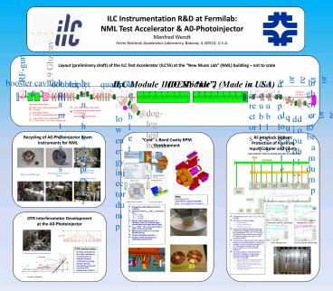
Layout (preliminary draft) of the ILC Test
Accelerator (ILCTA) at the New Muon Lab (NML)
building not to scale
beam trans.
high energy beam dump
booster cavities1 2
bunch compressor
3.9 Ghz cav
doublet
triplet
quads
dipole
doublet
doublet
doublet
correctors
correctors
dipole
RF-gun
ILC Module 1 (DESY kit)
ILC Module 2 (Made in USA)
19 meters
22 meters
C
O
PS
HOM couplers
HOM couplers
F
O
O
O
O
B
C
O
Y
B
B
T
Y
O
B
S
B
T
O
O
Y
O
O
B
S
T
O
B
B
O
B
O
B
T
O
B
O
B
B
B
test beam-line for advanced beam instrumentation,
e.g. EOS, Laser-wire, OTRI, cavity BPMs,
B
C
T
T
P
T
T
O
Basic beam instrumentation
B
B
T
Time-of-flight or beam phase monitor
Beam current / bunch charge monitor (T toroid)
O
dog-leg test beam-line (TBD)
B
B
doublet
Synchrotron light bunch length monitor (P pyro
detector)
quad
Beam position monitor (B button, PS
perpendicular stripline, C cavity)
low energy injector dump
dipole
doublet
correctors
TDB beam loss monitors (BLM)
Screen monitor (some multifunctional) (Y YaG,
O OTR, C CTR, S slit, F Faraday-cup)
Recycling of A0-Photoinjector Beam Instruments
for NML
RF Interlock System Protection of Klystron,
Input-Coupler and Cavity
Cold L-Band Cavity BPM Development
Screen monitors(OTR, slits, YaG)
Bunch arrival / beam phase pickup
Button-style BPM pickup
Faraday-cup monitor
Goal Development of acold CM-free L-Band
cavity BPM with lt 1 µm single bunch resolution
- Waveguide-loaded pillbox with slot coupling.
- Dimensioning for f010 and f110 symmetric to fRF
- fRF 1.3 GHz, - f010 1.1 GHz, - f110
1.5 GHz. - Dipole- and monopole ports, no reference cavity
for intensity signal normalization and signal
phase (sign). - Qload 600 ( 10 cross-talk at 300 ns
bunch-to-bunch spacing). - Minimization of the X-Y cross-talk (dimple
tuning). - Simple (cleanable) mechanics.
- Iteration of EM-simulations for optimizing all
dimensions.
- Developed for use in CC1, CC2, HTS, CTS NML
- RF interlock system design
- hardware-based,
- processor independent,
- VME64X implemented.
- Several RF interlock systems are now successfully
installed, commissioned and operated at CTS, CC1,
CC2 and HTS. A revised version will serve as
central RF interlock system for up to 3
cryo-modules at NML. - The primary purpose of the RF interlock system is
to protect klystron, cavity and coupler by
controlling the presence of RF. The system
removes the LLRF permit within 0.2-0.8 µs of
fault detection. - Normal operation Enable permit to LLRF and
modulator using analog hardware and digitize
signals for remote monitoring. - Klystron (FWD RFL power, window arcs PMT, RF
leak detection WG pressure). - Coupler (PMT, photodiode based arc detection and
FEP measurement, ceramic window temperature). - Cavity (PMT ard detection, vacuum control FEP
HOM couplers).
OTR Interferometer Development at the
A0-Photoinjector
OTR Interferometer A beam passing two thin
foils, allows the measurement of additional beam
parameters (energy, energy spread, divergence),
derived from the OTR interference pattern.
OTRI setup at the A0-Photoinjector
courtesy G. Kazakevich
2
ILC Instrumentation RD at Fermilab Collaboration
Activities Other EffortsManfred WendtFermi
National Accelerator Laboratory, Batavia, IL
60510, U.S.A.
Advanced Beam Instrumentation in the Optical
Domain
KEK/SLAC/FNAL ATF Damping Ring BPM Upgrade
Collaboration
DESY/SLAC/FNAL HOM Coupler Signal Analysis
Collaboration
- Optical diffraction radiation (ODR)
- Near field effect between EM fields of the beam
close to a conducting screen Intensity - DR impact parameter
- Non-intercepting beam measurement!
Near field ODR Monitoring (ANL/FNAL)
weak radiation
gtgt
DR
if a
TESLA 9-cell SC cavity and HOM coupler
TR
ltlt
courtesy A. Lumpkin
ATF DR button BPM characteristics
- EOS Bunch Length Measurement (ANL/FNAL/NIU)
- ZnTe Pockels effect
- Sampling Methods
- Scanning delay
- Spectral decoding
- Spatial decoding
- Temporal decoding
courtesy DESY
HOM coupler signals in time- and frequency domain
ATF DR tunnel hardware
ATF DR BPM upgrade overall block diagram
Higher order mode passbands below WG cutoff
Bunch Arrival / Beam Phase Monitor (DESY/FNAL)
- HOM as BPM
- TE111-6 narrow band read-out
- Beam-based calibration data, to orthogonalize the
polarization planes of the excited eigenmodes per
SVD algorithm. - 5 µm resolution
- HOM as phase monitor
- Comparison of the leaking 1.3 GHz fundamental
(TM010) to the first monopole HOM (TM011) - Broadband Scope analysis
- lt0.10 _at_ 1.3 GHz resolution
courtesy F. Loehl
ATF DR BPM upgrade VME hardware
- Martin-Puplett interferometer
- Needs many beam pulses to resolve the temporal
convolution - Difficult to calibrate the detectors
View from Top
ATF DR BPM upgrade block diagrams of analog and
digital signal processing hardware
Electron Bunch
Transition Radiation
courtesy R. Thurman-Keup
View from Top again
Mirrors
Wideband Mode Single BPM data shows trans. and
long. tunes.WB TBT resolution few µm!
Input Polarizer
Motorized stage
Polarizing Splitter
Coherent
Incoherent
Mirrors
Polarizing Splitter
Off-axis Paraboloidal Focusing Mirror
Pyro Detector 2
Pyro Detector 1
Narrowband Mode 128 kturns, 1kHz BWAfter 50 Hz
filter and single shot SVD analysisNB
resolution 200-400 nm!
- Detector elements
- Molectron pyro-electric (cheap, calibration)
- Golay cell (expensive)
Recommended
CrystalGraphics Presentations


