
Optical Activity - PowerPoint PPT Presentation
1 / 33
Title:
Optical Activity
Description:
Most naturally occurring materials do not exhibit chirality. ... If you'd like to look for signs of life on other planets, look for chirality. ... – PowerPoint PPT presentation
Number of Views:2063
Avg rating:3.0/5.0
Title: Optical Activity
1
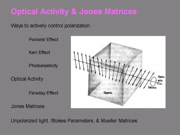
Optical Activity Jones Matrices
Ways to actively control polarization Pockels'
Effect Kerr Effect Photoelasticity Optical
Activity Faraday Effect Jones
Matrices Unpolarized light, Stokes Parameters,
Mueller Matrices
2
The Pockels' Effect
- An electric field can induce birefringence.
The Pockels' effect allows control over the
polarization rotation.
3
The Pockels Effect Electro-optic constants
4
The Q-Switch
In high-power lasers, we desire to prevent the
laser from lasing until weve finished dumping
all the energy into the laser medium. Then we
let it lase. A Pockels cell is the way we do
this. The Pockels cell switches (in a few
nanoseconds) from a quarter-wave plate to nothing.
After switching
Before switching
0 Polarizer
Mirror
0 Polarizer
Mirror
Pockels cell as an isotropic medium
Pockels cell as wave plate w/ axes at 45
Light becomes circular on the first pass and then
horizontal on the next and is then rejected by
the polarizer.
Light is unaffected by the Pockels cell and
hence is passed by the polarizer.
5
Q-switching
- Q-switching involves
- 1. Preventing the laser from lasing until the
flash lamp is finished flashing, and - 2. Abruptly allowing the laser to lase.
This yields a short giant high-power pulse. The
pulse length is limited by the round-trip time of
the laser and yields pulses 10 - 100 ns long.
6
The Kerr effect the polarization rotation is
proportional to the Kerr constant and E2
where Dn is the induced birefringence, E is
the electric field strength, K is the Kerr
constant of the material.
Use the Kerr effect in isotropic media, where the
Pockels' effect is zero. The "AC Kerr Effect"
creates birefringence using intense fields of a
light wave. Usually very high irradiances from
ultrashort laser pulses are required to create
quarter-wave rotations.
7
Photoelasticity Stress-induced Birefringence
- Clear plastic triangle between parallel and
crossed polarizers
Parallel
Crossed
You should see this in color!
8
Stress-Induced Birefringence in Diamond
An artificially grown diamond with nitrogen
impurities
Caused by strain associated with growth
boundaries
9
More Photoelasticity
- If there's not enough stress in a medium to begin
with, you can always add more yourself!
Clear plastic between crossed polarizers
You can use this effect to improve the
performance of polarizers.
10
Optical Activity (also called Chirality)
- Unlike birefringence, optical activity maintains
a linear polarization throughout. The
polarization rotation angle is proportional to
the distance. Optical activity was discovered in
1811 by Arago.
Some substances rotate the polarization clockwise
(dextrorotatory) and some produce a
counterclockwise rotation (levorotatory).
11
Right vs. left-handed materials
- Most naturally occurring materials do not exhibit
chirality. But those that do can be left- or
right-handed.
These forms of quartz, have the same chemical
formulas and structures, but are mirror images of
each other. One form of quartz rotates the
polarization clockwise and the other rotates it
counterclockwise.
12
Left-handed vs. right-handed molecules
The key molecules of life are almost all
left-handed. Sugar is one of the most chiral
substances known.
If youd like to look for signs of life on other
planets, look for chirality.
Occasionally, a molecule of the wrong chirality
can cause serious illness (e.g., thalidimide)
while its other enantiomer is harmless.
13
Principal Axes for Optical Activity
- As for birefringent media, the principal axes of
an optically active medium are the medium's
symmetry axes. - We consider the component of light along each
principal axis independently in the medium and
recombine them afterward. - In media with optical activity, the principal
axes correspond to circular polarizations.
14
Complex Principal Axes
- Usually, we write the E-field in terms of its x-
and y-components. - But we can equally well write it in terms of its
right and left - circular components.
When the principal axes of a medium are circular,
as they are when optical activity is present,
this is required. We must then decompose linear
polarization into its circular components
15
Math of Optical ActivityCircularPrincipal Axes
- At the entrance to an optically active medium, an
x-polarized beam (R L, neglecting the v2 in all
terms) will be
Note that this mess just adds up to x-polarized
light!
16
Math of Optical ActivityCircularPrincipal Axes
(contd)
- In optical activity, each circular polarization
can be regarded as - having a different refractive index, as in
birefringence. - After propagating through an optically active
medium of length d, - an x-polarized beam will be
17
Math of Optical ActivityCircularPrincipal Axes
(continued)
18
Math of Optical ActivityCircularPrincipal Axes
(continued)
19
The Faraday Effect
- A magnetic field can induce optical activity.
The Faraday effect allows control over the
polarization rotation.
20
The Faraday effect the polarization rotation is
proportional to the Verdet constant.
- b V B d
- where
- b is the polarization rotation angle,
- B is the magnetic field strength,
- d is the distance,
- V is the "Verdet constant" of the material.
21
To model the effect of a medium on
light'spolarization state, we use Jones matrices.
- Since we can write a polarization state as a
(Jones) vector, we use - matrices, A, to transform them from the input
polarization, E0, to the - output polarization, E1.
- This yields
- For example, an x-polarizer can be written
- So
22
Other Jones matrices
A y-polarizer
A half-wave plate
A half-wave plate rotates 45-degree-polarization
to -45-degree, and vice versa.
A quarter-wave plate
23
A wave plate is not a wave plate if its oriented
wrong.
0 or 90 Polarizer
Remember that a wave plate wants 45 (or
circular) polarization. If it sees, say, x
polarization, nothing happens.
Wave plate w/ axes at 0 or 90
AHWP
So use Jones matrices until youre really on top
of this!!!
24
Rotated Jones matrices
- Okay, so E1 A E0. What about when the
polarizer or wave plate - responsible for A is rotated by some angle, q ?
- Rotation of a vector by an angle q means
multiplication by a rotation - matrix
- where
- Rotating E1 by q and inserting the identity
matrix R(q)-1 R(q), we have - Thus
25
Rotated Jones matrix for a polarizer
- Applying this result to an x-polarizer
for small angles, e
26
Jones Matrices for standard components
27
To model the effect of many media on light's
polarization state, we use many Jones matrices.
- To model the effects of more than one component
on the polarization state, just multiply the
input polarization Jones vector by all of the
Jones matrices
A single Jones matrix (the product of the
individual Jones matrices) can describe the
combination of several components.
Remember to use the correct order!
28
Multiplying Jones Matrices
- Crossed polarizers
so no light leaks through.
Uncrossed polarizers (slightly)
So Iout e2 Iin,x
29
Recall that, when the phases of the x- and
y-polarizations fluctuate, the light is
"unpolarized."
- where qx(t) and qy(t) are functions that vary on
a time scale slower than - 1/w, but faster than you can measure.
- The polarization state (Jones vector) will be
- Unfortunately, this is difficult to analyze using
Jones matrices.
In practice, the amplitudes vary, too!
30
Stokes Parameters
- To treat fully, partially, or unpolarized light,
we define "Stokes parameters." - Suppose we have four detectors, three with
polarizers in front of them - 0 detects total irradiance.......................
.....................I0 - 1 detects horizontally polarized
irradiance.............I1 - 2 detects 45 polarized irradiance..............
..............I2 - 3 detects right circularly polarized
irradiance......I3 - The Stokes parameters
S0 º I0 S1 º 2I1 I0 S2 º 2I2
I0 S3 º 2I3 I0
1 for polarized light 0 for unpolarized light
31
Mueller Matrices multiply Stokes vectors
- We can write the four Stokes parameters in vector
form - And we can define matrices that multiply them,
- just as Jones matrices multiply Jones vectors.
To model the effects of more than one medium on
the polarization state, just multiply the input
polarization Stokes vector by all of the Mueller
matrices Sout M3 M2 M1 Sin
32
Stokes vectors (and Jones vectors for comparison)
33
Mueller Matrices (and Jones Matrices for
comparison)
Recommended
CrystalGraphics Presentations


