
Acoustic Anemometry Principle - PowerPoint PPT Presentation
1 / 9
Title:
Acoustic Anemometry Principle
Description:
Given ?f, , and d, v can be calculated using: Vairflow = (V12 V21)/2 ... Anemometer can measure phases of incoming acoustic signals and convert these phases to speed ... – PowerPoint PPT presentation
Number of Views:35
Avg rating:3.0/5.0
Title: Acoustic Anemometry Principle
1
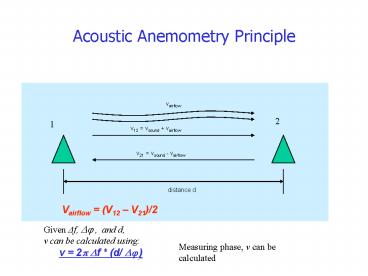
Acoustic Anemometry Principle
Vairflow (V12 V21)/2
Given ?f, ?? , and d, v can be
calculated using
Measuring phase, v can be calculated
v 2? ?f (d/ ?? )
2
Phase Measurement
??measured2
f1
f2
- Xreceived(t)Acos(2?f1t ??real )
- Multiply this received signal by a reference
cosine - Y(t) Acos(2?f1t ??real ) cos(2?f1t)
- A/2 cos(??real ) cos(2?(2f1)t
??real) - YDC1(t) A/2 cos(??real) After low pass
filtering the double frequency term - YDC2(t) A/2 sin(??real)
3
Implementation
Implementation on Pico Radio Test Bed
Expansion of Digital signal processing block
FPGA part has 16K gates. FPGA utilization is at
100
4
Direct Digital Frequency Synthesizer (DDFS)
Principle
Implementation
- f1 8.8kHz f2 8kHz
- 10 - phase accumulator bit
- 64 entry look-up table
- 9-bit outputs
DDFS output
5
Filters
- Two low pass filters 16 taps at fast clock rate
- 22 taps at slow clock rate
- Liner Phase FIR filters
- Using CSD representation, multiplying as truncate
and add, merge as a tree
Filter frequency responses
Filter implementation
6
Controller
- Implemented as a C program on the ARM
microprocessor - Conducts sharing of the FPGA datapath.
- Carries out averaging and inverse tangent
operations. - Synchronization is done by interrupts given by
FPGA.
7
Frequency Mismatch
- Frequency mismatch between transmitter and
receiver oscillators. - Sampling clocks generated on the FPGA have
different period. - Residual oscillation at foffset instead of a DC
signal
8
Results
Real acoustic input signal Phase estimates over
different distances
Clean synthetic input
9
Conclusions Future Work
- Conclusions
- Anemometer can measure phases of incoming
acoustic signals and convert these phases to
speed - Future Work
- Find a solution to frequency mismatch
- Provide synchronization to provide stand alone
operation - Increase wordlengths and improve accuracy
- Move to ultrasound operation
- (The last two involve changes on the hardware.)