
Review of 1 AC Circuit Fundamentals - PowerPoint PPT Presentation
1 / 21
Title:
Review of 1 AC Circuit Fundamentals
Description:
Real Power =I2 R (square of the rms current flowing ... Ammeter. 150V. 220V. Voltmeter. S/C Test (LV side. Shorted) O/C Test (HV side. Open) ... – PowerPoint PPT presentation
Number of Views:248
Avg rating:3.0/5.0
Title: Review of 1 AC Circuit Fundamentals
1
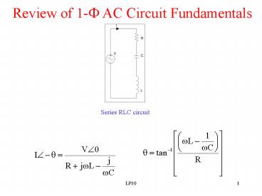
Review of 1-? AC Circuit Fundamentals
Series RLC circuit
2
Review of 1-? AC Circuit Fundamentals(1)
Power factor Cos ?
Apparent Power VI (multiply the rms value of
input voltage and current (ignore phase angle))
Real Power I2 R (square of the rms current
flowing through the reristor times the resistor
(ignore phase angle))
Series Resonance occurs when
is maximum in this case
3
Review of 1-? AC Circuit Fundamentals(3)
Parallel RLC circuit
Series Resonance occurs when
is minimum in this case
4
The Transformer
i1(t)
S1
S2
i2(t)
i1(t)
i2(t)
M
V2
e1(t)
e2(t)
Coil 2
Coil 1
(Secondary has N2 turns)
(Primary has N1 turns)
5
The Transformer(2)
- The source side is called Primary
- The load side is called Secondary
- Ideally
- The resistance of the coils are zero.
- The relative permeability of the core in
infinite. - Zero core or iron loss.
- Zero leakage flux
6
The Transformer(2)
- Switch S1 is closed and S2 is open at t0
- The core does not have a flux at t0
- We will now prove the following on the
greenboard - The voltage induced across each coil is
- proportional to its number of turns.
7
The Transformer(3)
ii) Switch S2 is now closed A
current now starts to flow in resistance R. This
current is i2(t) (flows out of the dotted
terminal).
Thus a MMF N2i2(t) is applied to the magnetic
circuit. This will immediately make a current
i1(t) flow into the dot of the primary side, so
that N1i1(t) opposes N2i2(t) and the original
flux in the core remains constant. Otherwise,
N2i2(t) would makethe core flux change
drastically and the balance between V1 and e1(t)
will be disturbed.
8
The Transformer(3)
- We will now prove the following on the
greenboard - The current induced in each coil is inversely
proportional to its number of turns. - Instantaneous input power to the transformer
Instantaneous output power from the transformer.
9
The Transformer(3)
Observation It was shown that the flux in the
core is ?m Sin(?t). Since the permeability of the
core is infinite ideally zero current can produce
this flux! In actuality, a current Im, known as
magnetizing current is required to setup the flux
in the transformer. This current is within 5 of
the full load current in a well designed
transformer.
L1 is the primary side self inductance.
10
Transformer Example(1)
N1N2 12
i) Find I1,I2 in the above transformer. Neglect
magnetizing current. ii) What is the reflected
(referred) load impedance on the primary
side iii) If the resistance is replaced by a)
100 mH inductor b) 10?F capacitance what will be
the reflected load impedance on the primary
side?
11
Transformer Example(1)
Solution on greenboard
12
Transformer Equivalent circuit (1)
I2
I1
INL
E1
E2
13
Transformer Equivalent circuit (2)
I2
I1
INL
14
Transformer Equivalent circuit (3)
I1
I2
INL
15
Transformer Equivalent circuit (4)
I1
I2'
INL
16
Open circuit Test
- It is used to determine Lm1 and Rc1
- Usually performed on the low voltage side
- The test is performed at rated voltage and
frequency under - no load
17
Short circuit Test
- It is used to determine Llp and Rp
- Usually performed on the high voltage side
- This test is performed at reduced voltage and
rated frequency with the output of the low
voltage winding short circuited such that rated
current flows on the high voltage side.
18
Transformer Regulation
- Loading changes the output voltage of a
transformer. - Transformer regulation is the measure of such a
deviation.
Definition of Regulation
Vno-load RMS voltage across the load terminals
without load V load RMS voltage across the
load terminals with a specified load
19
Transformer Losses and Efficiency
- Transformer Losses
- Core Loss V12 / Rc1
- Copper Loss I12 R1 I22 R2
Definition of efficiency
load power factor
20
Another Transformer Example
The following are the open circuit and short
circuit test data of a single phase, 10 kVA,
2200/220V, 60 Hz transformer
i)Find the equivalent circuit with respect to HV
and LV side ii) Find the efficiency and
regulation of the transformer when supplying
rated load at 0.8 pf lag.
21
Transformer Example(2)
Solution on greenboard
Recommended
CrystalGraphics Presentations


