
Data Modeling and Database Design - PowerPoint PPT Presentation
1 / 150
Title:
Data Modeling and Database Design
Description:
2. Wood, J. and Silver, D. Joint Application Design: How to Design Quality ... We start the data modeling in the ISP stage by identifying subject areas with ... – PowerPoint PPT presentation
Number of Views:2806
Avg rating:3.0/5.0
Title: Data Modeling and Database Design
1
Data Modeling and Database Design
- Minder Chen, Ph.D.
- mchen_at_gmu.edu
2
Data Modeling and Database Design Course Outline
- INTRODUCTION
- Introduction to Data Modeling
- Database Development Life Cycle Overview
- ENTITY AND RELATIONSHIP
- Develop the Subject Area Diagram
- Develop Preliminary Data Model Entity
Relationship Identification - ATTRIBUTES AND SUBTYPES
- Attributes Identification and Definition
- Develop Fully Attributed Data Model
- Identifiers
- Data Modeling Exercise
- Partitioning and Entity Subtypes
- NORMALIZATION
- Normalization
- Normalization Exercise
- De-normalization
- DATA MODEL EVALUATION AND MAPPING TO RELATIONAL
DBMS - Refine a Data Model Analysis and Simplification
- Transform to Physical Data Base Design
3
References
- Data Modeling and Database Design
- 1. Batini, Ceri, Navathe, Conceptual Database
Design, Redwood City, CA The Benjamin/Cummings
Publishing Company, Inc., 1992. - 2. Teorey, T. J., Database Modeling and Design
The Entity-Relationship Approach, Morgan Kaufmann
Publishers, Inc., 1990. - 3. Thomas A. Bruce, Designing Quality Databases
with IDEF1X Information Models, Dorset House
Publishing, NY New York, 1991. - 4. Texas Instruments, A Guide to IE Using IEF,
2nd edition, Part No. 2739756-0001, 1990. - 5. Martin, James, Information Engineering Book
II Planning and Analysis, Prentice-Hall Inc.,
1989. - 6. Dave Ensor, Ian Stevenson, Oracle Design,
O'Reilly Associates, 1997 - 7. Rob Gillette, etc., Physical Database Design
for Sybase SQL Server, Prentice Hall, 1995. - 8. Ralph Kimball, The Data Warehouse Toolkit,
Wiley, 1996. - JAD References
- 1. August, J. H.. Joint Application Design The
Group Session Approach to System Design.
Englewood Cliffs, NY, Prentice Hall, Inc., 1991. - 2. Wood, J. and Silver, D. Joint Application
Design How to Design Quality Systems in 40 Less
Time. New York, NY, John Wiley Sons, 1989. - 3. Andrews, D. C. and Leventhal, N. S., Fusion
Integrating IE, CASE, and JAD A Handbook for
Reengineering the Systems Organization, Englewood
Cliffs, NJ Yourdon Press, 1993.
4
Data Modeling and Database Design INTRODUCTION
- Systems Development Life Cycle (SDLC) in a
Client/Server Environment - Introduction to Data Modeling
- Database Development Life Cycle Overview
5
Rationales for Data Modeling
- Data is the foundation of modern information
systems enabled by data base technologies. - Data in an organization exist and can be
described independently of how these data are
used. - Data should be managed as a corporate-wide
resource. - The types of data used in an organization do not
change very much. - Data have certain inherent properties which lead
to correct structuring. - If we structure data according to their inherent
properties, the structure (i.e., data models)
will be stable.
6
History of Data Modeling
- Importance of Entity-Relationship Modeling
Technique - Database
- Data modeling and enterprise-wide data
- Data quality
- Data updating and accessing tools and procedure
- Data sharing culture
- ER modeling technique was first developed by
Peter Chen in 1976 - A conceptual/logical data modeling tool
- A user-oriented approach
- A graphic-based method
- ER modeling technique is the major data modeling
method in Information Engineering and is widely
supported by most of CASE tools. - Data modeling is the foundation of most
database-centered transaction processing systems
and data warehouse systems
7
CSC Development Strategies
HIGH
- RE-CREATE new business process systems from
scratch - RE-ENGINEER business process systems
- RE-DESIGN current systems
- RE-HOST current systems
- RE-IMAGE current systems
Risk Long Term Reward Short Term Costs Degree of
Change
LOW
8
Distribution of Business Function (Logic)
Presentation Space
Presentation Service
Presentation Logic
Function Logic
Data Logic
Data Service
Data Space
Server
Client
- Functions that access data on the server
- Functions that need input from multiple users
- Functions that coordinate the work of several user
- Presentation logic
- Local input validation
- Output production logic
- Local peripheral drivers
- Performance critical processing
- Issues
- Distribution of data
- Platform-specific capabilities and
interoperability - Connectivity capabilities/platform
- Frequency of change to codes
- Configuration management
9
C/S Development Methodology
performance
SDLC
rules
Conceptual Analysis
Physical Design
Logical Design
C/S Architecture
Work Flow
Form Sequences
Forms, Screens
User Interface
Process Flow
Object Interaction Model
Programs, Procedures
Application Logic
Data Model
Database Schema
Tables, Indexes
Information Data Base
Source David Vaskevitch, Client/Server
Strategies, IDG Books, 1993.
10
Client/Server Application Development Methodology
Where Do You Start?
Requirements
Information Data Base
Processes Behavior
Workflow User Interface
Architecture
Application Design and Development
Source David Vaskevitch, Client/Server
Strategies, IDG Books, 1993.
11
Data Modeling (Data Base Design) Process
Information Requirements
A conceptual DB schema is a high-level
description of the database, independent of the
particular DBMS.
Conceptual DB Design
Conceptual (Enterprise) DB Schema
A logical DB schema is a description of the
structure of the database that can be processed
by a DBMS relational, network, or hierarchical.
Logical DB Design
Logical DB Schema
- A physical DB schema is a description of the
implementation of the database in external
memory it describes the storage structures and
access methods used in order to effectively
access and maintain data.
Physical DB Design
Physical DB Schema
Source Batini, C., Ceri, S., and Navathe, S. B.,
Conceptual Database Design An Entity-Relationship
Approach, The Benjamin/Cummings Publishing
Company, Inc., 1992.
12
Multiple Perspectives
13
Data Model (Entity Relationship Diagram)
is enrolled under
placed by
Member
Member
Agreement
applies to
places
Order
established by
sells
generates
established
is sold on
generated by
sponsors
is featured in
Club
Promotion
Product
is sponsored by
features
14
Entity Relationship Diagram Subject Area and
Entity Type
- Subject Area and Subject Area Diagram
- Entity Types
- Entity Instances
- Finding Entity Types
- Evaluating Entity Types
15
Subject Area (Submodel)
- A natural area of interest to the business that
is centered on a major resource, inputs, outputs,
or activity of the business. - It contains a set of entity types.
- We start the data modeling in the ISP stage by
identifying subject areas with names and
descriptions. - In BAA stage, subject areas are used to as high
level grouping of entity types. - Naming a subject area is a noun in plural form
and often has the name as the central entity type
in the subject area. - Examples
Projects
Project Member
Task
Project
16
Subject Area Diagram
Raw-materials
Products
Customers
Orders
Suppliers
Sales-persons
Purchase Orders
Buyers
Legends
Subject Area
Association
17
Entity Types
- Definition
- An entity is an object or event, real or
abstract, about which we would like to store
data. Entity is the abbreviation of entity
type. It represent a set of entity instances
which can be described by the same set of
attribute types. The value of the same attribute
for each entity instance may be different. - Identifying Entity Types
- What information is required by the business?
- Things that are of interest to the business that
need to be remembered in order to manage and
track them. - Things belong to the same entity type have common
characteristics.
18
Naming Entity Types
- The name of each entity is in singular form
- a noun
- an adjective a noun
- a noun a noun (noun string)
- an adjective a noun a noun
- Examples
- Customer, Customer Order, Product, Hourly
Employee, Project, Department, Unfilled Customer
Order - Be clear and concise
- Avoid abbreviation
- Be consist with users terminology
- Identify synonyms
- Customer Client
- Product Merchandise
- Supplier Vendor
- Teacher Faculty
- Use one name as the official name and document
others as aliases
19
Exercise Entity Type Naming
- Courses
- Department
- Customer Order
- PO
20
Properties of Entity Types
- Name
- Description
- Identifier
- Properties Estimated number (Max., Min.,
Average) of entity instances - Expected growth rate of entity instances
- Subject Area in which the Entity Type resides
- Attributes that describe the Entity Types
- Examples of entity type instances
21
Definition of an Entity Type
- A poor definition of Customer Anyone that buys
something from the company. - Can employees be a customer?
- Can a leasor be a customer?
- If the company sold a subsidiary to another
company, does the new owner consider a customer? - Good definition should be
- Compatible
- Precise
- Concise
- Clear
- Complete
22
Good Definition
- Compatible
- Customer An ORGANIZATION that purchase PRODUCTs
for personal use. - Distributor An ORGANIZATION that purchase
PRODUCTs for resale. - Precision
- With appropriate qualifiers
- Example An ORGANIZATION is considered to have
purchase a PRODUCT when we receive a valid
PURCHASE ORDER from it. - Complete
- ORGANIZATION, PRODUCT, PURCHASE ORDER need to be
defined. - Concise and Clear
- Use modular definition
23
Example of Entity Type Descriptions
Entity Type
Description
Customer
Information about all persons or organizations
who purchases
Product
All goods manufactured and sold
Raw-material
Components used to manufacture Products.
Supplier
Vendors of Raw Materials.
Buyer
Company personnel responsible for purchasing
Raw-Materials from Suppliers
24
Entity Type and Entity Instance (Occurrence)
- Entity Types Entity Instance
- Vendor ABC Co.
- Employee John Smith
- Course Intro. to IE
- Department Marketing Department
25
Exercise Entity Types or Entity Instances?
- Maryland
- Organization Unit
- Customer
- President
- Bill Clinton
- Department of Commerce
- Address
26
Finding Entity Types
- Interviews with users
- JAD workshops
- Business forms
- Reports
- Computer files using reverse engineering
- Operation manuals
27
Where to Look for an Entity Type?
- Tangible or Intangible Things
- The nouns that are used to describe the problem
domain will often correspond to the major Entity
Types of the system, at least at a high level. - Examples Product, Sensor, and Employee,
Department, and Sale Office. - Resources
- Any resources that an organization needs to
manage should be represented as an Entity Type.
Information assists the efficient and effective
use of other resources through improved decision.
- Examples Inventory, Machine, Bank Account, and
Customer. - Roles Played
- Roles can be played by persons or organizational
units. - Examples Customers, Managers, and Account
representatives. - Events
- Events are incidents that occur at points in
time. An event often involved an interaction
between two Entity Types or an action that
changes the status of an Entity Type. - Examples Sale, Delivery, and Registration of a
motor vehicle.
28
BIAIT Business Information Analysis and
Integration Technique
- Analysis of Orders
- Ordered entities can be a thing, a space, or a
skill. - View the order from supplier side.
- If an organization receives no orders, it has no
reason for existing. - An organization unit can receive multiple types
of orders. - 4 questions about the Supplier
- Billing (Cash)?
- Deliver Late (Immediate)?
- Profile customer?
- Negotiate price (Fixed)?
- 3 questions about the Ordered Entity
- Rented (Sold)?
- Tracked?
- Made to order (Stock)?
Source Carlson, W. M., "BIAIT Business
Information Analysis and Integration Technique -
The New Horizon," Data Base, Vol.
10, No. 4, 1979, pp. 3-9.
29
Criteria for Evaluating an Entity Type
- Need to be remembered by the information system
in order to be functional. - Can be operated on CREATE, READ, UPDATE, DELETE.
- Has a set of operations/services that always
apply to change the status of each occurrence of
an Entity Type. - Carry a set of attributes that always apply to
describe each occurrence of an Entity Type. - Have at least one relationship with other entity
type. - Exist more than one entity occurrence (instance)
in an Entity Type. - Have at least a unique identifier.
- Domain-based requirements Something that the
system must have in order to operate. These may
be clearly specified in the problem description
or known from subject matter experts.
30
Entity Relationship Modeling and Diagramming
- Relationships
- Entity Relationship Diagramming Notation
- Attributes
- Identifiers
- Partitioning and Entity Subtypes
31
Relationship (Type)
- Definition
- A Relationship Type is an association among
Entity Types. It indicates that there is a
business relationship between these Entity Types.
- Relationship Membership is the participation of
an Entity Type in a Relationship. - In IE, a Relationship Type can involve only two
Entity Types (binary relationship). Some other
modeling techniques allow n-ary relationships. - Examples
- CUSTOMER places ORDER
- ORDER is placed by CUSTOMER
- EMPLOYEE works on PROJECT
- PROJECT has project member EMPLOYEE
32
Paring (Relationship Instance)
- Relationship paring is a pair of Entity Instances
of two Entity Types associated by a Relationship
Type between these two Entity Types.
Entity Types
Entity Instance
Student
Student1 Student2
Course
CourseA CourseB CourseC CourseD
Relationship
Relationship Paring
Student takes Course
Student1 takes CourseA Student1 takes
CourseB Student1 takes CourseD Student2 takes
CourseA Student2 takes CourseC Student2 takes
CourseD
33
Relationship Instances Grouping
- Definition A collection of pairings of a
Relationship Membership in which an Entity
Instance is involved. - Examples
- Student1 takes CourseA, B, and D
- Student2 takes CourseA, C, and D
- CourseA is taken by Student1 and Student2
34
Relationship Cardinality
E2
E1
One-to-One
11
E2
One-to-Many
E1
1M
E2
Many-to-Many
E1
MN
35
Relationship Cardinality
- The number of Entity Instances involved in the
Relationship Instances Grouping in a Relationship
Type. - Three Forms of Cardinality
- 1. One-to-one (11)
- DEPARTMENT has MANAGER
- Each DEPARTMENT has one and only one MANAGER
- Each MANAGER manages one and only one DEPARTMENT
- 2. One-to-many (1m)
- CUSTOMER places ORDER
- Each CUSTOMER sometimes (95) place one or more
ORDERs - Each ORDER always is placed by exactly one
CUSTOMER - 3. Many-to-many (mn)
- INSTRUCTOR teaches COURSE
- Each INSTRUCTION teaches zero, one, or more
COURSEs - Each COURSE is taught by one or more INSTRUCTORs
36
Entity Relationship Diagram (ERD) Notations
Graphical Notations
Cardinality indicator
zero
one
many
relationship-description
Entity-Y
Entity-X
reversed-relation-description
min max
Translate into two structured statements
Each Entity-X relationship-description
cardinality-indicator (one-or-many) Entity-Y
Each Entity-Y reversed-relationship-description
(zero-or-one) Entity-Y
Example
is-managed-by
Manager
Department
manages
37
Optionality of Relationship Memberships
- Whether all entity instances of both entity types
need to participate in relationship pairing. - Optionality
- Mandatory
- Optional
- Example
- CUSTOMER membership is optional
- ORDER membership is mandatory
places
ORDER
CUSTOMER
is placed by
38
Relationship Statements
one
Cardinality indicator
one or more
Graphical Notations
places
ORDER
CUSTOMER
is placed by
zero (sometimes)
Optionality indicator
one (always)
Each Entity X optionality relationship
cardinality Entity Y
Each CUSTOMER sometimes places one or more
ORDER. Each ORDER always is placed by one
CUSTOMER.
39
Defining Relationships
- Name
- Description
- Property
- Cardinality volumes
- Optionality percentage of Entity Type X's
instances pairing with Entity Type's Y's
instances - Transferability A relationship is transferable
if an entity instance can change its pairing
within the same relationship. - TRANSFERABLE An EMPLOYEE can change to a
different DEPARTMENT. - NON-TRANSFERABLE An ORDER cannot be transferred
to another CUSTOMER.
40
ERD More Examples
places
(a)
Customer
Order
belongs-to
is-contained-in
Product
contains
Parallel Relationship
(b)
manages
Project
Employee
is-managed-by
works-for
has-project-members
is-consists-of
(c)
Involuted or Looped Relationship
Part
contained-in
41
ERD Alternative Notations
places
Customer
Order
belongs-to
Alternative Notations
places
Customer
Order
belongs-to
places
Customer
Order
belongs-to
1
M
places
Customer
Order
42
Identifying Relationships
- Association between entity types
- Entity types that are used on the same forms or
documents. - A description in a business document that has a
verb that relates two entity types - has
- consists of
- uses
43
Attributes
- Definition
- Characteristics that could be used to describe
Entity Types and Relationship Types. However, in
IE, relationship types are not allowed to have
attributes. - Naming Conventions
- Names that have business meaning
- Don't use abbreviation or possessive case, e.g.,
PN and Customer's name - Don't include entity type name because IEF will
prefix the attribute name with entity type name
automatically - Use standard format
- Entity Type Name (Qualifiers) Domain Name
- Customer Name
- Employee Starting Date
- Examples
- Customer has customer name, address, and
telephone number - Product has quantity-on-hand, weight, volume,
color, and name. - Employee has SSN, salary, and birthday.
- Employee-works-for-project has percentage-of-time,
starting-date.
44
Attributes Notations
Student ID
Student
Student Name
Student
studentID
Birth date
name phone
Student ID
Course no.
enrollment
Birth date
Student(Student ID, Student Name, Birth Date)
- Finding Attributes
- Attributes are identified progressively during
BAA phase. - Data Analysis
- Activity Analysis
- Interaction Analysis
- Current Systems Analysis
45
Attribute Value
- Definition
- Attribute Values are instances of Attributes used
to describe specific Entity Instances - Examples
- Customer Number 011334
- Customer Name Minder Chen
- State VA
- Order Total 23,000
- Sale tax 250
- An attribute of an entity type should have only
one value at any given time. (No repeating
group) - Avoid using complex coding scheme for an
attribute. - For example PART Number X-XXX-XXX
Part Type Material Sequence Number
46
Type Instance
- OBJECT TYPE OCCURRENCE
- Entity Type Entity Instance
- Entity Entity Instance
- Entity Type Entity
- Relationship (Type) Pairing (Relationship
Instance) - Attribute (Type) (Attribute) Value
47
Attribute Source Categories
- Basic
- Definition An Attribute Value that cannot be
deduced or calculated. - Examples Student name and Birthday
- Derived
- Definition The Attribute Value can be calculated
or deduced from relationship Groupings or from
the values of other Attributes. The value of a
Derived Attribute changes constantly. - Examples Student Age, Account Balance, Number of
courses taken. - Designed
- Definition The Attribute is created to overcome
the system constraints. The value of a Designed
Attribute does not change. - Examples Student ID, Course number.
48
Data Types
49
Properties of Attributes
- Name
- Description
- Attribute Source Category Basic, Derived,
Designed - Domain or data type Text, Number, Date, Time,
Timestamp - Optionality Mandatory or optional
- Length and/or precision
- Permitted Values (Legal Values)
- Ranges
- A set of values (Code Table)
- Default value or algorithm
- Tools such as PowerBuilder has additional
properties for tables columns called extended
attributes - Validation Rule
- Editing Format
- Reporting Format
- Column Heading
- Form Label
- Code Table
50
Composite Attribute
- Definition
- Example
- Telephone Number
- Area code Exchange Extension
- There is no support of composite attribute type
most of CASE tools. In such case, an composite
attribute must be stored as an entity type.
51
Domain
- A collection of values which can be taken by one
or more attributes. - Date is the domain for Ordered Date, Student's
Birthday, Employee Starting Date. - A used defined domain can have customized
validation rules and formats. - CASE tools such as IEF only supports the
following basic domains - Text
- Number
- Date
- Time
- Timestamp
52
Identifiers
- The identifier of an entity type is a set of
attributes and/or relationships whose values can
uniquely identify an entity. - Entity types should have one identifier.
- Identifiers may consist of
- A single attribute Student ID
- A set of attributes Students ID Course ID
- An attribute and a relationship membership
(implemented as a foreign Key) Order Item No
Order Has Order Item
53
Identifying Relationship
product
customer
Symbol for Identifying Relationship
is ordered by
places
ORDERS
is placed by
has
contains
order item
order
is part of
54
Data Modeling Case Study
- The following is description by a pharmacy owner
- "Jack Smith catches a cold and what he suspects
is a flu virus. He makes an appointment with his
family doctor who confirm his diagnosis. The
doctor prescribes an antibiotic and nasal
decongestant tablets. Jack leaves the doctor's
office and drives to his local drug store. The
pharmacist packages the medication and types the
labels for pill bottles. The label includes
information about customer, the doctor who
prescribe the drug, the drug (e.g., Penicillin),
when to take it, and how often, the content of
the pill (250 mg), the number of refills,
expiration date, and the date of purchase." - Please develop a data model for the entities and
relationships within the context of pharmacy.
Also develop a definition for "prescription".
List all your underlying assumptions used in your
data models.
55
Data Modeling Case Study
- Given the following narrative description of
entities and their relationships, prepare a draft
entity relationship diagram (ERD). Be sure any
reasonable assumptions that you are making. - Burger World Distribution Center serves as a
supplier to 45 Burger World franchises. You are
involved with a project to build a database
system for distribution. Each franchise submits
a day-by-day projection of sales for each of
Burger World's menu products - the products
listed on the menu at each restaurant - for the
coming month. All menu product require
ingredients and/or packaging items. Based on
projected sales for the store, the system must
generate a day-by-day and ingredients need and
then collapse those needs into one-per-week
purchase requisitions and shipments.
56
Data Modeling Process
- List entity types
- Create relationships
- Pick a central entity type
- Work around the neighborhood
- Add entity types to the diagram
- Build relationships among them
- Determine cardinalities of relationships
- Find/Create identifiers for each entity type
- Add attributes to the entity type in the data
model - Analyze and revise the data model
57
Classifying Attribute and Partitioning
- An Entity Subtype A collection of Entities of the
same type to which a narrower definition and
additional Attributes and Relationships apply.
An Entity Subtype inherits (retains) all the
Attributes and Relationships of its parent Entity
Type. - Classifying Attribute An attribute of the Base
Entity Type whose values partition the Entity
Instances into Subtypes. - Partitioning A basis for subdividing one entity
type into subtypes. The process of dividing an
Entity Type into several Subtypes based on a
Classifying Attribute is called Partitioning. - The Classifying Attribute is recorded as a
property of the Partitioning and it appears on
the diagram.
58
Characteristics of Partitioning
- Optionality
- Mandatory Every Entity instances of the Entity
Type must fall into one of the Subtype
categories. - Optional Not every Entity instances of the
Entity Type must fall into one of the Subtype
categories. - Entity Life Cycle The states through which an
Entity Type can pass are used for Partitioning. - Enumeration
- Fully enumerated
- Not fully enumerated
- Classifying Attributes and Values
- Classifying Attribute Type
- D Domestic Subtype
- F Foreign Subtype
59
Partitioning and Entity Subtype Notation
ATTRIBUTE Employee ID Name Birthday
ATTRIBUTE Teaching Quality Indicator
Employee
Type
Teaches
Lecturer
Seminar
Staff
Status
Wage
Hourly
60
Alternative Notations for Subtypes
IDEF1X
PowerDesigner
- Complete Category
- All categories shown
employeeID name phone
employee type
part-time-emp
full-time-emp
employeeID (FK) hourly-rate
employeeID (FK) salary
61
Entity Subtype Partitioning
Life Cycle Partitioning
Order
Order Status
Taken
Scheduled
Shipped
Billed
Paid
62
Normalization
- A data base is a model or an image of the
reality. - Logical Data Base Design is a process of modeling
and capturing the end-user views of an
application domain and synthesis them into a data
base structure. - Normalization is a logical data base design
method. - The basis for normalization is the functional
dependencies among attributes in a table.
63
SQL Terminology
Column
Product Table
p_no product_name quantity price 101 Color
TV 24 500 201 BW TV 10 250 202 PC 5 2000
Row
Create a table in SQL
CREATE TABLES
(p_no CHAR(5) NOT NULL, product_name CHAR(20)
, quantity SMALLINT, price DECIMAL(10,
2))
64
SQL Terminology
- Set Theory Relational DB File Example
- Relation Table File Product_table
- Attribute Column Data item Product_name
- Tuple Row Record Product_101's info.
- Domain Pool of legal values Data type DATE
65
SQL Principles
- The result of a SQL query is always a table (View
or Dynamic Table) - Rows in a table are considered to be unordered
- Dominate the markets since late 1980s
- Can be used in interactive programming
environments - Provide both data definition language (DDL) and
data manipulation language (DML) - A non-procedural language
- Can be embedded in 3GL
- Embedded SQL
- Dynamic SQL
66
SQL Data Definition Language (DDL)
TABLE VIEW INDEX DATABASE
CREATE DROP
ALTER
TABLE
67
SQL Introduction
- A relational data base is perceived by its users
as a collection of tables - E. F. Codd 1969
- Dominate the markets since late 1980s
- Strengths
- Simplicity
- End-user orientation
- Standardization
- Value-based instead of pointer-based
- Endorsed by major computer companies
- Most CASE products support the development of
relational data base centered applications
68
SQL Data Manipulation Language (DML)
- p_no product_name quantity price
- 101 Color TV 24 500
- 201 BW TV 10 250
- 202 PC 5 2000
SELECT UPDATE INSERT DELETE
The Generic Form of the SELECT Statement
SELECT DISTINCT column(s) FROM table(s) WHERE
conditions GROUP BY column(s) HAVING
condition ORDER BY column(s)
69
Database Table
- The following code retrieves only the Last Name
and the Employee ID where the Employee ID is
greater than 5. The records are retrieved in
descending order. - SELECT LastName, EmployeeID
- FROM Employees
- WHERE EmployeeID 5
- ORDER BY EmployeeID DESC
70
WHERE Clause
- WHERE Use the Where clause to limit the
selection. The symbol indicates literal date
values. - SELECT FROM Employees
- WHERE LastName "Smith"
- SELECT Employees.LastName FROM Employees
- WHERE Employees.State in ('NY','WA')
- SELECT OrderID FROM Orders
- WHERE OrderDate BETWEEN 01/01/93 AND
01/31/93
71
Keys
- A key, also called identifier, is an Attribute or
a Composite Attribute that can be used to
uniquely identify an instance of an entity type. - Examples
- Entity Type Key
- Warehouse Warehouse Number
- Product Product Number
- Student Student ID or SSN
- Ship Name and Port of Registration
- Stock of Product Product Number and Warehouse
No.
72
Types of Key
- Primary Key A unique key is an attribute or a
set of attributes that has been used by the DBMS
as the identifier of a table. - Candidate (Alternative) Key An attribute or a
set of attributes that could have been used as
the primary key of a table. - Secondary (Index) Key An attribute or a set of
attributes that has been used to construct the
data retrieval index. - Concatenated (Combined or Composite) Key A set
of attributes that has been used as the key. - Foreign Key An attribute or a set of attributes
that is used as the primary key in another table.
73
Purposes of Normalization
- Avoid maintenance problems such as Update .
- Insert There may be no place to insert new
information. - Delete Some important information will be lost
by deletion. - Update Inconsistency may occur because of the
existence of data redundancy. - Provide maximum flexibility to meet future
information needs by keeping tables corresponding
to object types in their simplified forms.
74
A Common Sense Approach to Normalization
- Don't rush to put all the information in one
table. - Create a table to correspond to a class of a
simple object type that should exist by itself,
i.e., "one fact in one place." - Include common fields (links) as ways of joining
information from several related tables. - Avoid redundancy by using links to retrieve data
from related tables.
75
Normalization Theory
- Normalization is a process of systematically
breaking a complex table into simpler ones. - It is built around the concept of normal forms.
- A relation is in a particular normal form if it
satisfies a specific set of constraints such as
dependencies among attributes in the relation. - For x is an integer and x 1,
if a relation is in x-NF
than it is in (x-1)-NF. - Higher order normal forms are usually more
desirable than lower order normal forms. - Normalization process usually starts from complex
relations which are usually drawn from some
existing documents such as business forms.
76
A Business Form
77
An Informal Example of Normalization
- A CUSTOMER ORDER contains the following
information - OrderNo
- OrderDate
- CustNo
- CustAddress
- CustType
- Tax
- Total
- one or more than one Order-Item which has
- ProductNo
- Description
- Quantity
- UnitPrice
- Subtotal.
78
Solution
Unnormalized table
(OrderNo, OrderDate, CustNo, CustAddress,
CustType, Tax, Total, 1ProductNo, Description,
Quantity, UnitPrice,Subtotaln)
Remove repeating group
(OrderNo, ProductNo, Description, Quantity,
UnitPrice, Subtotal)
1st NF
Remove partial FD
(OrderNo, OrderDate, CustNo, CustAddress,
CustType, Tax, Total)
2nd NF
Remove transitive FD
(OrderNo, ProductNo, Quantity, UnitPrice,
Subtotal)
(ProductNo, Description, UnitPrice)
(OrderNo, OrderDate, CustNo, Tax, Total)
3rd NF
(CustNo, CustAddress, CustType)
79
Unnormalized Form
- A relation that has multi-valued attributes
(repeating groups). - Normalization Process Remove Multi-value
Attributes - If an unnormalized relation R has a primary key K
and a multi-value attribute M, the normalization
process is - The multi-value attribute M should be removed
from R. - A new relation will be created with (K,M) as the
primary key of the relation. - There may be some other attributes associated
with this new relation. - R will then be at least in 1NF.
- Example An Employee relation has an attribute
language-spoken. For some employees there may
be more than one language that they can speak.
EMP (employeeID, empName, empAddress, (language1,
language2, ...)) ò EMP (employeeID, empName,
empAddress) EMP-LANGUAGE (employeeID, language,
skillLevel)
80
How Do You Remove the Repeating Groups?
- CREATE TABLE MEM_CONDITION (
- MEMBER VARCHAR2(12) NOT NULL,
- CASE VARCHAR2(16) NOT NULL,
- DIAG_ARRAY_1 VARCHAR2(6) NOT NULL,
- DIAG_ARRAY_2 VARCHAR2(6) NOT NULL,
- DIAG_ARRAY_3 VARCHAR2(6) NOT NULL,
- DIAG_ARRAY_4 VARCHAR2(6) NOT NULL,
- DIAG_ARRAY_5 VARCHAR2(6) NOT NULL,
- DIAG_EX_ARRAY_1 VARCHAR2(2) NOT NULL,
- DIAG_EX_ARRAY_2 VARCHAR2(2) NOT NULL,
- DIAG_EX_ARRAY_3 VARCHAR2(2) NOT NULL,
- DIAG_EX_ARRAY_4 VARCHAR2(2) NOT NULL,
- DIAG_EX_ARRAY_5 VARCHAR2(2) NOT NULL,
- DRUG_ARRAY_1 VARCHAR2(12) NOT NULL,
- DRUG_ARRAY_2 VARCHAR2(12) NOT NULL,
- DRUG_ARRAY_3 VARCHAR2(12) NOT NULL,
- DRUG_ARRAY_4 VARCHAR2(12) NOT NULL,
- DRUG_ARRAY_5 VARCHAR2(12) NOT NULL,
- LC_ARRAY_1 VARCHAR2(4) NOT NULL,
81
Functional Dependency
- Notation R.X R.Y
- Definition Attribute Y of Relation R is
functionally dependent on the Attribute X of
Relation R when there is each value of R.Y
associated with no more than one value of R.X.
R.X and R.Y may be composite attributes. - Description
- R .Y is functionally dependent on R.X
- R.X functionally determines R.Y
82
Full Partial Dependency
- R.A R.B
- If B is not functionally dependent on any subset
of A (other than A itself), B is fully dependent
on A in R. - If B is functionally dependent on a subset of A
(other than A itself), B is partially dependent
on A in R.
83
First Normal Form (1NF)
- A relation R is in the first normal form (1NF) if
and only if all attributes of any tuple in R
contain only atomic values. - Normalization Process
- Remove Partial Functional Dependencies
- If R is in 1NF and has a composite primary key
(K1,K2), an attribute P is functionally dependent
on K1 (K1 P) (i.e., P is partially dependent
on (K1, K2)), the normalization process is - The attribute P should be removed from R and a
new relation will be created with K1 as the
primary key and P as a non-key attribute. - A relation that is in 1NF and not in 2NF must
have a composite primary key. - Example
- Supplier-Part relation has attributes supplier,
part, qty, city, distance, where (supplier,
part) is the key. - City is partially dependent on supplier.
SUPPLIER-PART (supplier, part, qty, city,
distance) ò SUPPLIER-PART (supplier, Part,
qty) SUPPLIER (supplier, city, distance)
84
Non-loss Decomposition
- Normalization is a reduction (decomposition)
process that replaces a relation by suitable
projections. Each of the projection is a new
relation that is in a further normalized form
than the original relation. The collection of
projections is equivalent to the original
relation. - The original relation can always be recovered by
taking the natural join of these projections. - Any information that can be derived from the
original relation can also be derived from the
further normalized relations. The converse is
not true. - The process is reversible because no information
is loss in the reduction process.
85
Transitive Dependency
- In a relation R,
- if R.A R.B and R.B R.C
- then attribute C is said to be transitively
dependent on attribute A.
86
Second Normal Form (2NF)
- A relation R is in the second normal form (2NF)
if and only if it is in 1NF and every non-key
attribute is fully dependent on the primary key. - Normalization Process Remove Transitive
Dependencies - If R is in 2NF and has two non-key attributes A1
and A2 where A2 is functionally dependent on A1
(A1 A2). The A2 should be removed from R and
a new relation will be created with A1 as the
primary key and A2 as a non-key attribute. - Example
- Supplier relation has attributes supplier, city,
distance, where supplier is the key and distance
to a supplier can be determined by the city of
the supplier.
SUPPLIER (supplier, city, distance,
quality_level) ò SUPPLIER (Supplier, city,
quality_level) CITY-DISTANCE (city, distance)
87
Third Normal Form (3NF)
- A relation R is in the third normal form (3NF) if
and only if the non-key attributes (if there is
any) are fully dependent on the primary key of R
(i.e., R is in its 2NF) and are mutually
independent. - Heuristic to Check Whether a Relation Is in 3NF
- All the non-key attributes (which are not
multi-value attributes) are dependent on the
(primary) key, the whole key, and nothing but the
key.
Explanation
- All the non-key attributes have atomic value and
dependent on the key (1NF - No multi-value
attribute), - the whole key, (2NF - No Partially Functional
Dependency) - and nothing but the key (3NF - No Transitive
Functional Dependency)
88
Normalization Process
Unnormalized Form
F
G
B
C
D
E
H
A
remove repeating groups
1NF
2NF
B
C
D
E
A
F
G
H
A
remove transitive dependencies
remove partial dependencies
3NF
3NF
3NF
D
E
3NF
F
G
A
F
H
A
D
B
C
89
Normalization Pros and Cons
- Pros
- Reduce data redundancy space required
- Enhance data consistency
- Enforce data integrity
- Reduce update cost
- Provide maximum flexibility in responding ad hoc
queries - Cons
- Many complex queries will be slower because joins
have to be performed to retrieve relevant data
from several normalized tables - Programmers/users have to understand the
underlying data model of an database application
in order to perform proper joins among several
tables - The formulation of multiple-level queries is a
nontrivial task.
90
Join Two Tables
- SELECT Categories.CategoryName,
Products.ProductName - FROM Categories, Products
- WHERE Products.CategoryID
Categories.Category ID
91
Tables in Relational DB
- Identify Primary Keys and Foreign Keys in the
following Tables!!!
ID
92
Join Tables
- SELECT Orders.OrderID, Orders.CustID,
LastName, Firstname, Orders.ItemID,
Description - FROM Customer, Orders, Inventory
- WHERE Customer.CustID Orders.CustID AND
- Orders.ItemID Inventory.ItemID
- ORDER BY CustID, Orders.ItemID
ID
ID
93
Foreign Keys Primary Keys in a Sample Access
Database
94
An Example of a Complex Query
Please list name and phone number of customers
who have ordered product number 007.
- SELECT customer_name, customer_phone
- FROM customer
- WHERE customer_number IN
- SELECT customer_number
- FROM order
- WHERE order_no IN
- SELECT order_no
- FROM orderItem
- WHERE product_number 007
95
Denormalization
- The process of intentionally backing away from
normalization to improve performance.
Denormalization should not be the first choice
for improving performance and should only be used
for fine tuning a database for a particular
application. - Requirements
- Prior normalization
- Knowledge of data usage
- Benefits
- Minimize the need for joins
- Reduce number of tables
- Reduce number of foreign keys
- Reduce number of indices
- Knowledge of Data Usage
- How often are two data items needed together
- How many rows are involved
- How volatile is denormalized data
- How important is visibility of data to users
- What is the minimum response time and frequency
of an query
96
De-normalization An Example
JOIN
R2
R1
Denormalization
R2
R1 R 2
- Where
- R1 (ProductNo, SupplierNo, Price)
- R2 (SupplierNo, Name, Address, Phone)
- R1R2 (ProductNo, SupplierNo, Name, Address,
Phone, Price) - R2 should be kept to prevent data loss.
- Data redundancy in R1R2 and R2 could cause
potential data inconsistency problems if the
redundant data in these two tables are not
maintained properly.
97
Data Model Refinement and Transformation
- Data Model Refinement
- Associative Entity Type
- Removing Many-to-Many Relationships
- Keys
- Transformation to Relational Databases
98
Refinement of a Data Model Analysis and
Simplification
- Isolated Entity Type
- Solitary Entity Type
- One-to-One Relationship
- Redundant Relationship
- Multi-Valued Attributes
- Attribute with Attributes
- Many-to-Many Relationship
99
Isolated Entity Type
- An Entity Type that does not participate in a
Relationship. - Since every Entity Type should participate in at
least one Relationship, there exist two
alternatives - Identify a relevant Relationship
- Remove the Entity Type from the model
100
Solitary Entity Type
- An Entity Type that has only one Entity Instance.
Examples Computer Center, Sales Tax, and
Current Order Number. Solitary Entity Types may
be too restrictive. - Alternatives
- Introduce another Entity Type with a wider scope.
- Computer Center Organization Unit
- Define it as an Attribute of an Entity Type.
- Sales Tax Sales Tax of Order
- Define it as a data element in an parameter
table. A parameter table has only one row. - Current Order Number Current Order Number of
Parameter Table
101
Evaluate One-to-One Relationship
- It may be an unnecessary relationship between two
Entity Types if they have the same attribute and
relationships (i.e., they are identical). - It should be then combined into one Entity Type.
Maybe Incorrect
becomes
Purchase Request
Purchase Order
has request
Correct
Purchase Order
102
Redundant Relationship
Is this relationship redundant?
has ordered
product
customer
is ordered by
places
ORDERS
is placed by
has
contains
order item
order
is part of
- Differences in timing of an entity type in its
life cycle - Implemented as separate entity types or use
subtypes - Use value of attributes or additional attributes
to differentiate them
103
Redundant Relationship
Redundant
Warehouse
Product
stocks
is held as
holds
Stock
contains
is held in
Non-redundant
is contained in
is contained in
Order Line
Product
Order
contains
contains
is placed by
places
is contained in
is contained in
Customer
Order History
contains
contains
104
Multi-Valued Attribute
- Definition
- An Attribute that may have more than one value at
a time is called a multi-valued attribute. - Solution
- Create an Entity Type for the multi-valued
attribute - Example
- Languages spoken by an Employee
- Employee(ID, Name, Phone, Languages)
- Employee(111, John Smith, 201-999-8888,
(English, Chinese)) - Employee(ID, Name, Phone)
- Employee(111, John Smith, 210-999-8888)
- Employee_language(ID, Language)
- Employee_language(111, English)
- Employee_language(111, Chinese)
105
Attribute with Attributes
- An Attribute that can be described by other
Attributes is called an attribute with
attributes. - Example
- College Degree by an Employee
- (John Smith has a College Degree in Computer
Sciences from George Mason University) - Solution
- Create an Entity Type to avoid an Attribute with
Attributes. - Add new attributes to the existing Entity Type.
106
Associative Entity Type
- An Associative Entity Type is an Entity Type
whose existence is meaningful only if it
participates in several (2) Relationship Types
at the same time. - Associative Entity Types are often introduced to
represent additional information in many-to-many
Relationships or to decompose a many-to-many
Relationship into two one-to-many Relationships. - Associative Entity Types are also used to
represent n-ary Relationships in a binary data
model.
107
Remove Many-to-Many Relationship
Given
contains
Order
Product
belongs-to
Why?
- There is no place to attach Attributes that are
required to describe a many-to-many Relationship.
- It is difficult to translate many-to-many
Relationships into relational tables
automatically.
How?
A many-to-many relationship can be decomposed
into two one-to-many Relationships by creating
an Associative Entity Type between the existing
two Entity Types.
has
contains
Order
Product
Order Line
belongs to
is contained in
108
Remove Many-to-Many Relationships Exercises
Remove the many-to-many relationship from the
following ER diagrams
(a)
has-sources
Product
Supplier
offers
(b)
takes
Student
Course
is-taken-by
consists-of
(c)
Part
is-contained-in
109
Bills of Material
A
Part
C
B
is-a-component-in
consists-of
1
2
D
E
D
F
Product Structure
3
1
2
2
Product-Structure(Parent Part No, Child Part No,
Quantity)
A B 2 A C 1 B D 1 B E 3 C D 2 C F 2
110
Using an Associative Entity Type to Represent an
N-ary Relationship
involved in product usage
involved in product usage
Product
Project
involved in product usage
Supplier
Product Usage is an Associative Entity Type for a
3-ary Relationship.
is used in
uses
Product Usage
Product
Project
supplies
Supplier
111
Translate Data Models to Relational Tables
Given
has
contains
Order
Product
Order Line
is contained in
belongs to
Key Product Attribute Description
Qty-on-hand Unit Price
Key Order Attribute Order date Customer ID
Sale Person ID
Key OrderProduct Attribute Quantity Unit
Price
Relational Tables Created
- CREATE TABLE ORDER
- (OrderNo CHAR(10) NOT NULL,
- OrderDate DATE,
- CustomerID CHAR(10),
- SalePersonID CHAR(10))
112
Transformation of Data Models to Relational
Database Tables
- The entire, or part of, a data
(entity-relationship) model can be translated
into a normalized database design. - Objects Created
- At most one relational database
- One or more relations (tables)
- Data structures (DDL) representing the elements
(attributes) and the primary key of each relation
- Data type of each data elements
113
Heuristics of Transformation
- A table is created for each Entity Type in the ER
diagram. - A table is created for each multi-valued
attribute. - Relationship Types are implemented as tables or
as foreign keys in other tables. - Many-to-many relationship types are translated
into tables. - Foreign keys are used for implementing one-to-one
and one-to-many Relationship Types. - For one-to-many Relationship Types, the foreign
key is placed in the table that represents the
Entity Type on the "many" end of the Relationship
Type. - For identifying one-to-many Relationship Types,
the PK of the "one" table migrate to the "many"
table as a FK and the FK is also part of the PK
of the "many" table. - For non-identifying one-to-many Relationship
Types, the PK of the "one" table migrate to the
"many" table as a FK and the FK is a non-key
attribute of the "many" table.
114
PowerDesign Data Architect
Generation/Reverse Engineering
CDM, PDM
Generation Reverse Engineering
Generation Reverse Engineering
Extended Attributes
Database Structure
Database Structure
Triggers Stored Procedures
Target
http//www.powersoft.com/
4GL Tool
Target DBMS
115
PowerDesigner
116
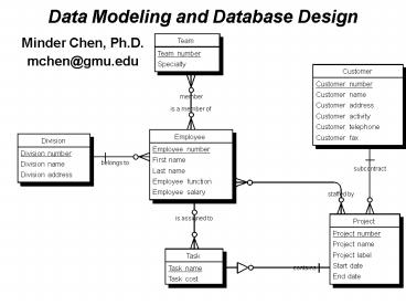
A Sample Conceptual Data Model
Team
Division
Team number
Customer
Division number
Speciality
Customer number
Division name
Customer name
Division address
Customer address
Customer activity
Is member of
supervises
Customer telephone
Customer fax
Employee
Employee number
First name
Last name
Activity
Subcontract
Uses
Employee function
Start date
Employee salary
End date
Is manager of
Project
Task
Material
Project number
Task name
Project name
Material number
Task cost
Project label
Material name
Material type
Participate
composes
composed of
Start date
End date
117
Notations
Entity
Relationship
One-to-many
118
More on Relationships
Employee
is a member of
Employee number
First name
Team
Last name
Team number
Employee function
Specialty
member
Employee salary
Many-to-many cardinality
Project
Task
Project number
Task name
Project name
Task cost
Project label
A project 'contains one or more tasks, and a
task's existence is dependent on the project.
119
Advanced Concepts
Material
Material number
Material name
Account
Material type
Account Number
Name
composes
composed of
Savings
Checking
Rate
Fees
Employee
Employee number
Subtype
First name
Last name
Employee function
Employee salary
Reflexive relationship
120
Define Entities
121
Define Attributes
122
Check Parameters
123
Relationship Definition
124
Dependent (Identifying Relationship)
- Check the box to indicate a dependent
relationship. "One to many" and "mandatory" are
automatically chosen as the cardinality and
optionality. - At the physical data model level, the parent
entity type's primary key (PK) will become part
of the dependent child entity type's PK. It is
also a foreign key.
125
Inheritance (Super-Type and Sub-Type)
126
Generate Physical Data Model
127
Physical Data Model
Conceptual Data Model
Transformation
Do not define FK as an attribute.
Physical Data Model
DIVNUM DIVNUM
DIVNUM automatically migrates as a foreign key.
128
Dependent Relationship
Conceptual Data Model
Project
Task
Project number
Task name
Project name
Task cost
Project label
Transformation
Physical Data Model
PROJECT
PRONUM
TASK
CUSNUM
PRONUM
PRONUM PRONUM
EMPNUM
TSKNAME
ACTBEG
ACTBEG
ACTEND
ACTEND
PRONAME
TSKCOST
PROLABL
129
Physical Data Model
Physical Data Model
Project
Management
Model
Project Management
Author
User
Version
6.x
7/21/98
TEAM
TEANUM
CUSTOMER
TEASPE
EMPLOYE_MATERIAL
DIVISION
CUSNUM
DIVNUM
MATERIAL.MATNAME
char(30)
CUSNAME
PROJ.EMPLOYEE.EMPNUM
numeric(5)
DIVNAME
CUSADDR
TEANUM TEANUM
DIVADDR
PROJ.EMPLOYEE.EMPFNAM
char(30)
CUSACT
PROJ.EMPLOYEE.EMPLNAM
char(30)
CUSTEL
MEMBER
PROJ.EMPLOYEE.EMPFUNC
char(30)
CUSFAX
TEANUM
MATERIAL
EMPNUM
PROJ.EMPLOYEE
USED
DIVNUM DIVNUM
CUSNUM CUSNUM
EMPNUM EMPNUM
USED
EMPNUM EMP_EMPNUM
MATNUM
EMPNUM
PROJECT
EMPLOYEE
EMPNUM EMPNUM
PRONUM
EMPNUM
CUSNUM
MATNUM MATNUM
EMP_EMPNUM
EMPNUM EMPNUM
EMPNUM
DIVNUM
ACTBEG
EMPFNAM
ACTEND
EMPLNAM
MATERIAL
PRONAME
EMPFUNC
MATNUM
PROLABL
EMPSAL
MATNAME
MATTYPE
PRONUM PRONUM
MATNUM CPD_MATNUM
EMPNUM EMPNUM
MATNUM CPN_MATNUM
TASK
PARTICIPATE
PRONUM
PRONUM PRONUM
PRONUM
COMPOSE
Recommended
CrystalGraphics Presentations


