
Snmek 1 - PowerPoint PPT Presentation
1 / 27
Title:
Snmek 1
Description:
The SDD long-range system is designed for strategic ... operation gives SDD the ultimate concealment and security feature of 'seeing without being seen' ... – PowerPoint PPT presentation
Number of Views:102
Avg rating:3.0/5.0
Title: Snmek 1
1
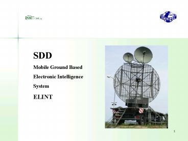
SDD Mobile Ground Based Electronic
Intelligence System ELINT
2
Main Features
- The SDD long-range system is designed for
strategic reconnaissance, monitoring and tracking
of naval and ground radar targets.
- The passive principle of operation
gives SDD the ultimate concealment and security
feature of seeing without being seen. - High sensitivity of the system allows
reception of the signal reflected from the
trophosphere, thus ensuring working range beoynd
radio horizon up to a distance of 650 700 km. - Perfect analysis of the received
signal enables to get full information about the
type and position of the targets.
3
Applications
- The system is first of all designed for
reconnaissance of a wide range of ground and
naval RF sources within an extensive
reconnaissance area (up to 700km and 360?). - Basic types of sources
- naval radars
- air defence and surveillance radars
- artillery radars
- CW emitters
- different types of pulse emitters
4
Typical targets processed in SDD frequency band
0,8 - 4 GHz
4 - 8 GHz
8 - 12 GHz
-ground and naval military surveillance and air
defence radars -airport surveillance radars
-SAM and artillery radars
-civil naval radars -CW emitters -tracking SAM
and artillery radars
5
SDD - Configuration
- The SDD system consists of two or more identical
DF stations. - Each DF station contains
- AU antenna unit (antennas and HF receiving
devices) - PCU and evaluation unit (receiving electronic
devices, evaluation and control workstation,
analysis workstation, communication systems)
The PCU is located in ISO 1D shelter. The system
can be transported by any heavy-duty truck or
railway wagon.
6
SDD - Railway Transport
7
SDD - Configuration
Total view on the SDD shelter
8
SDD - Basic Principles
of reconnaissance using of tropospheric
propagation of signals (beyond radio horizon)
STRATOSPHERE
SCATTER VOLUME
TROPOSPHERE
EARTH
Range up to 700 km
9
SDD - Basic Principles
Monopulse method serving to find source direction
points where the signal intersects the antenna
system beams
DF
RF source
??
The receiving antenna system consists of two
beams.
The received information is processed in
principle from one pulse it means that processed
information is independent on troposcatter
fading effect.
10
SDD - Basic Principles
Target Location
Result -target position coordinates-target
type and parameters
Target (x,y)
Transmission of -time of signal arrival -DF
position coordinates-received signal
azimuth-signal technical parameters and type
radio or telephone data link
DF1 master(x1 ,y1)
DF2 slave (x2 , y2)
radio or telephone data link
to command and control center
11
SDD - Location accuracy diagram
s- iso-line of the target error (km) R- x,y
target range(km)
Baseline 80 km
12
SDD - Basic Principles of processed bandwith
8 - 12 GHz OPTIONAL
Total processed bandwith
0.8 GHz
8 GHz
4 GHz
?
Instantaneous frequency bandwith for monitoring
100 MHz
20 MHz
?
4 MHz
Frequency bandwith for analysis and DF
1 MHz
13
SDD - System design
14
SDD - System design-block scheme of DF station
15
SDD - Operational Modes
- MODE 1 - automatic retrieval of new
sources - MODE 2 - automatic checking of known
sources - MODE 3 - manual direction finding and
detailed signal analysis - MODE 4 - area determination of source
location by means of paired DF stations
16
SDD - Operational Modes
- MODE 1 - automatic retrieval of new sources
retrieval conditions
parameters of the source found
found sources
checked frequency steps
17
SDD - Operational Modes
- MODE 2 - quick automatic checking of known
sources based on database list
resultant parameters the source checked last
list of sources to be checked
checked sources
data relating to the source under check
the source being checked - data collection
18
SDD - Operational Modes
- MODE 3 - signal time analysis
numerical values
time behaviour PRI of pulses
time behaviour PW of pulses
time behaviour CF of pulses
19
SDD - Operational Modes
- MODE 3 - digital filtering
digital filtering
histograms of PRI
histogram of PW
histogram of CF
20
SDD - Operation Modes
- MODE 3 - detailed analysis of individual pulses
from measuring unit
numerical display of measured pulse parameters
21
SDD - Operation Modes
- MODE 4 - area determination of source location
by paired DF stations
the same source detected
different sources detected
22
SDD - Operation Modes
- MODE 4 - area determination of source location by
paired - DF stations - position calculation
resultant location
azimuth obtained from one DF station
position of DF stations
azimuth obtained from the other DF station
23
SDD - Technical Parameters
Frequency range 0,8 GHz - 8 GHz
optional 8 GHz - 12 GHz
24
SDD - Technical Parameters
- Receiving sensitivity - 84 dBm at 20
MHz BW - (without antenna gain)
- Antenna gain 25 to 35
dB (31 to 41 dB for analysys in - subband 2 to 8 GHz)
- Instantaneous dynamic range gt 50dB
- DF accuracy lt 0.5 RMS
- Frequency accuracy 1 MHz
- After statistical processing 0.1
MHz
25
SDD - Technical Parameters
- Pulse width range (PW) 0.1 to 1600 µs
- Pulse repetition interval (PRI) 2 µs to 0.8 s
- Amplitude range gt50dB (step 1dB)
- Radar antenna rotation period 0.02 to 100 s
26
SDD - Technical Parameters
- Antenna elevation - 1.5 to 4.5 degree
(can be changed) - Area of coverage 360 degree
- Emitter library 1000 and more
- Types of display all types of
operating displays and system status
displays
27
SDD - Technical Parameters
Recommended
CrystalGraphics Presentations


