
UWB communication systems transmit pulses instead of modulated sine waves - PowerPoint PPT Presentation
1 / 9
Title:
UWB communication systems transmit pulses instead of modulated sine waves
Description:
Taking pulse-shape design into account adds one more dimension to improve the ... power can be delivered, but it's shape is 3D. Input. Microstrip Antenna ... – PowerPoint PPT presentation
Number of Views:125
Avg rating:3.0/5.0
Title: UWB communication systems transmit pulses instead of modulated sine waves
1
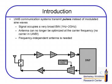
Introduction
- UWB communication systems transmit pulses instead
of modulated sine waves - Signal occupies a very broad BW (1Hz2GHz)
- Antenna can no longer be optimized at the carrier
frequency (no carrier in UWB!) - Frequency-independent antenna is needed
DSP
2
Challenges in UWB Antenna Design
- EM aspects of UWB communication systems have not
been studied adequately - Most of the conventional antenna analyses assume
harmonic time dependent (not the case in UWB) - Time-domain EM analysis/simulation are needed
- Issues in UWB antenna design
- Efficient pulse generation/reception
- Pulse dispersion problem
- Matching/Ringing problem
3
System Design Perspective
- UWB antenna is not likely to be a purely
resistive load and may strongly influence the
transmitter circuits - Antenna/circuit co-design is necessary
- Efficient pulse-shape design
- Taking pulse-shape design into account adds one
more dimension to improve the performance of the
antenna
Pulse Generator
Transmission Line
Bonding Wire
Antenna
4
Antenna Specifications
- Requirements of UWB antenna
- 2-Dimensional
- Omni-directional field pattern
- Small size
- Low cost
- Possible candidates
- Dipole antenna
- Loop antenna
- Microstrip antenna
5
Dipole Antenna
- Consists of two straight wires
- Simple scheme, easy to analyze, mechanism
is well-known - Popular in narrow-band systems
- Humps in frequency domain
- Resistively loaded dipoles exhibit very broad BW
since reflection on the antenna is suppressed,
but - Radiation efficiency is reduced
- Termination is a problem
Feed point
6
Loop Antenna
- Circular turns of wire
- To meet the 2D geometry spec only 1 turn is used
- Used for AM radio
- Radiate normally/axially if the loop is
small/large relative to a wavelength - A modified version, Large Current Radiator, is
adopted by Aether Wire Location, Inc., an UWB
localizer company. Large radiation power can be
delivered, but its shape is 3D
Input
7
Microstrip Antenna
- Metallic patches sit on a dielectric substrate
- Usually made on PCB
- Low profile, conformable to various surfaces,
inexpensive, durable, but narrow-band - Modify the shape to broaden the bandwidth, e.g.
bowtie antenna
Dielectric substrate
Antenna Patch
ground
8
EM Simulation Tool
- Remcom XFDTD
- Full-wave EM simulator based on Finite Difference
Time Domain method - Ex. Monopole antenna on a conducting box
9
Future Work
- Establish performance evaluation procedure in
XFDTD and compare different antenna schemes - According to reciprocity theorem, we can simply
look at the transmitting antenna in early
simulation - Important parameters of the transmitting antenna
s11, input impedance, radiation pattern, etc. - After thorough investigation by simulation, build
the antenna on PCB and experiment its
practicability - Transmitter design
- Pulse generator design
- Simulation of the antenna/circuit interface
- Combine SPICE/Spectre and XFDTD
Recommended
CrystalGraphics Presentations


