
The Efficiency Variation Between Wave Power Generator Structures PowerPoint PPT Presentation
1 / 1
Title: The Efficiency Variation Between Wave Power Generator Structures
1
The Efficiency Variation Between Wave Power
Generator Structures
How? This project entails making two Permanent
Magnet Generator Buoys and testing the voltage
output. Using 1 PVC pipe 10 long, wire is wound
around the pipe. Two wires exit the buoy, one
from the top of the stack and the other from the
bottom, and ar connected to a voltage meter
hooked up to laptops. The 3/8 inch neodymium disc
magnets are stacked two at a time on a metal rod
with similar sides facing each other, causing
them to repel, acting as the translator. In
between each set of two magnets, four bolts that
are one half of the width of a magnet are
attached to keep the magnets in place. In the
buoy float design, the translator is attached to
a rubber band, with a k constant of 24.9, so that
the stack of magnets can move with some tension.
The tension allows for the magnetic fields to
change generate electricity. Attached to the
bottom of the translator is a weight to help the
buoy stay upright and keeps the buoy in place.
The pile design uses a tier structure to support
the buoy. To simulate the tier, a broomstick was
used. The translator was attached to the
broomstick vertically. The PVC pipe and the coils
fit over the magnets. When the waves pass by the
buoy and PVC pipe will oscillate creating
electricity. Data was collected at Osburn
Acuatic Center using a 3 foot 6 inch deep pool.
The figures were acquired with the use of voltage
meters were collected at 15 second intervals.
Because the trials were done the same each time,
thus any error in the calculations were the
result of errors in the equipment.
Why? In a world where global warming and
declining natural resources are ever growing and
ominous problems, renewable energy sources are .
Wave power has become the new undiscovered
frontier in energy possibilities. Unlike dams,
the structures used to capture wave power do not
impede on the life of the marine animals. Waves
will be a constant source of power unlike wind
power. This study focuses on Permanent Magnet
Linear Generator Buoys, one of the more untested
and un-researched designs for wave power.
By Erik Bateham, Justin Chi, and Kelly Wells
What? By building pile and float designs to
test, we can compare and contrast how effective
they are in similar situations. To limit the
variations between the two types, we used the
same structure and setup besides the form of
movement, one being spring and the other
requiring waves to push. For the structure, as
explained in the picture, as the waves oscillate,
the structure will move up and the magnet will
move up and down, changing the magnetic field,
which produces electricity with metal wires
coiled on the surrounding edge. The use of the
magnets with strong ratings and small size forms
a tremendous magnetic field. Researchers believe
that the buoys are capable of producing 250kw
each. This estimate is based on much larger
PMLGs than the prototypes used in this
experiment.
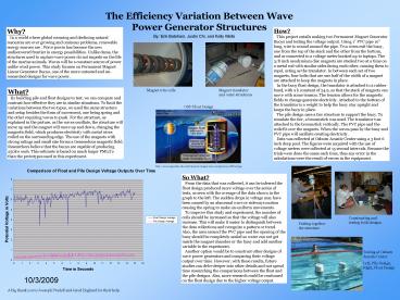
So What? From the data that was collected, it
can be inferred the float design produced more
voltage over the series of tests, as seen with
the average of the data shown in the graph to the
left. The sudden drops in voltage may have been
caused by an abnormal wave or sideways motion
causing the spring to make un-uniform movements.
To improve this study and experiment, the
number of coils should be increased so that the
voltage will also increase. This will make it
easier to distinguish between the data
collections and recognize a pattern or trend.
Also, the area around the PVC pipe and the
opening of the buoy should be completely sealed
so water can not get inside the magnet chamber or
the buoy and add another variable to the
experiment. Another option would be to
construct other designs of wave power generators
and comparing their voltage output over time.
However, with these results, future studies can
delve deeper into other details and not spend
time researching the comparisons between the
float and the pile designs. Also, more research
could be continued on the float design due to the
higher voltage output.
Constructing and testing both designs
Putting together the structure
Testing at Osburn Acuatic Center Left, Pile
Design, Right, Float Design
A big thank you to Joeseph Prudell and Jared
Englund for their help.
Recommended
