
PEElectrical Review Course Class 2 AC Circuits - PowerPoint PPT Presentation
1 / 37
Title:
PEElectrical Review Course Class 2 AC Circuits
Description:
1) Identify properties of periodic waveforms and calculate the DC and RMS values ... the handout 'Complex Numbers using the Casio fx-115MS' that contains examples of ... – PowerPoint PPT presentation
Number of Views:251
Avg rating:3.0/5.0
Title: PEElectrical Review Course Class 2 AC Circuits
1
PE-Electrical Review Course - Class 2 (AC
Circuits)
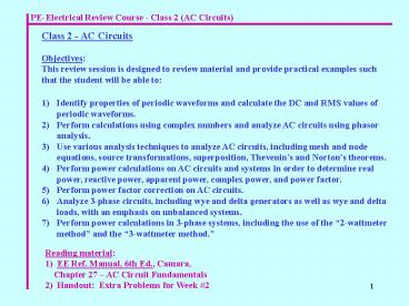
Class 2 - AC Circuits Objectives This review
session is designed to review material and
provide practical examples such that the student
will be able to
1) Identify properties of periodic waveforms and
calculate the DC and RMS values of periodic
waveforms. 2) Perform calculations using complex
numbers and analyze AC circuits using phasor
analysis. 3) Use various analysis techniques to
analyze AC circuits, including mesh and node
equations, source transformations, superposition,
Thevenins and Nortons theorems. 4) Perform
power calculations on AC circuits and systems in
order to determine real power, reactive power,
apparent power, complex power, and power
factor. 5) Perform power factor correction on AC
circuits. 6) Analyze 3-phase circuits, including
wye and delta generators as well as wye and delta
loads, with an emphasis on unbalanced
systems. 7) Perform power calculations in 3-phase
systems, including the use of the 2-wattmeter
method and the 3-wattmeter method.
Reading material 1) EE Ref. Manual, 6th Ed.,
Camara, Chapter 27 AC Circuit
Fundamentals 2) Handout Extra Problems for
Week 2
2
PE-Electrical Review Course - Class 2 (AC
Circuits)
Waveforms Periodic Waveforms A periodic
waveform satisfies the relationship v(t1) v(t1
T) where T period (in seconds) f frequency
(in Hertz, Hz) w radian frequency (in rad/s)
Sinusoidal Waveforms Sinusoidal waveforms are
periodic waveforms described by v(t) Vpcos(wt
? ) where Vp peak or maximum voltage
and ? phase angle in degrees where a shift to
the left is positive and a shift to the right is
negative (as with any function)
3
PE-Electrical Review Course - Class 2 (AC
Circuits)
Leading and Lagging Waveforms A waveform leads
another when a specific point on the waveform
(such as a zero crossing) occurs earlier in time
than it does for the second waveform. In the
example shown, V1 leads V2 by angle q
and V2 lags V1 by angle q
Note The time difference, tD, between V1 and
V2 can be converted to an angle using
Average (DC) Value of Periodic Waveforms VDC
VAVG DC or average voltage, which is defined as
follows Similarly,
Two ways to find the average (DC) value 1) By
inspection (or by using a simple or weighted
average) 2) By integration (using the integral
definitions shown above)
4
PE-Electrical Review Course - Class 2 (AC
Circuits)
Example 1
Find the average value, IAVG , of the following
periodic waveform
Example 2
Find the average value, VAVG , of the following
periodic waveform
5
PE-Electrical Review Course - Class 2 (AC
Circuits)
Example 3
Find the average value, VDC , of the following
periodic waveform (the output of an ideal
half-wave rectifier)
6
PE-Electrical Review Course - Class 2 (AC
Circuits)
RMS Value of Periodic Waveforms VRMS VEFF
Root-Mean-Square (RMS) or effective voltage,
which is defined as follows Similarly,
The name Root-Mean-Square essentially gives the
definition VRMS the square-root of the average
value of the function squared Two ways to find
the RMS value 1) By inspection (square the
function, find its average, and take the square
root) 2) By integration (using the integral
definitions shown above)
7
PE-Electrical Review Course - Class 2 (AC
Circuits)
Example 4
Find the RMS value of the following periodic
waveform
Find the RMS value of the following periodic
sinusoidal waveform
Example 5
8
PE-Electrical Review Course - Class 2 (AC
Circuits)
Example 6
Find the RMS value of the following periodic
waveform
Example 7
A household AC outlet is commonly described by
VRMS 120V and f 60 Hz. a) Describe the
waveform as a function v(t) b) Sketch the
waveform showing the peak value and the time for
each of the first 2 periods.
9
PE-Electrical Review Course - Class 2 (AC
Circuits)
AC Circuit Analysis (also called sinusoidal
steady-state analysis or phasor analysis) Before
reviewing AC Circuit Analysis, a review of
complex numbers is useful. Complex Numbers A
complex number can be expressed in two
forms 1) Rectangular form
2) Polar form
10
PE-Electrical Review Course - Class 2 (AC
Circuits)
Converting between rectangular form and polar
form
Convert 10 j20 to polar form.
Example 8
Convert 25/30o to rectangular form.
Example 9
Converting between rectangular form and polar
form using calculators See the handout Complex
Numbers using the Casio fx-115MS that contains
examples of complex number calculations for AC
circuits.
Demonstrate complex number calculations using one
or more of the calculators listed above.
Demonstration
11
PE-Electrical Review Course - Class 2 (AC
Circuits)
Definition A phasor is a complex number in
polar form that represents magnitude and phase
angle of a sinusoidal voltage or current.
Express each quantity below in the other form.
Example 10
Phasors - relative quantities Discuss each of
the following a) should phasors use sin or cos
as a reference? b) should phasors use peak or
RMS voltages for the magnitudes?
12
PE-Electrical Review Course - Class 2 (AC
Circuits)
Complex Impedances Components are represented
in AC circuits as follows Z impedance or
complex impedance (in ?)
Resistors
Capacitors
Inductors
KVL and KCL in AC Circuits KVL and KCL are
satisfied in AC circuits using phasor voltages
and currents. They are not satisfied using the
magnitudes of the voltages and the currents.
Consider how KVL applies to the RL circuit below
in both the time-domain and in the phasor domain.
13
PE-Electrical Review Course - Class 2 (AC
Circuits)
AC Circuit Analysis Procedure 1) Draw the phasor
circuit A) Represent voltage and current sources
as phasors B) Represent components (resistors,
inductors, and capacitors) as complex
impedances. 2) Analyze the circuit in the same
way that you might analyze a DC circuit. (For
example, you can combine series/parallel
impedances like you would resistances and you can
use node equations, mesh equations, source
transformations, voltage and current division,
superposition, etc., to analyze the
circuit.) 3) Convert the final phasor result back
to the time domain.
14
PE-Electrical Review Course - Class 2 (AC
Circuits)
Example 11
Analyze the circuit shown below using phasor
analysis.
15
PE-Electrical Review Course - Class 2 (AC
Circuits)
Complex Power In DC circuits we often calculate
P, real or average power. In AC circuits,
several terms related to power are often used.
Also note that the use of phasors with RMS values
is very convenient for power calculations.
I
RMS
Z
VRMS
_
16
PE-Electrical Review Course - Class 2 (AC
Circuits)
Example 12
Determine the real power, reactive power, complex
power, apparent power, and power factor for the
circuit shown below (include units with each
answer). Note that this is the same circuit used
in Example 11. Find the power quantities using
the total current from Example 11 and the
relationship
17
PE-Electrical Review Course - Class 2 (AC
Circuits)
Other Useful Relationships for Calculating Power
Quantities Power delivered by the source Power
dissipated by the circuit so another way to
calculate power is to find the power dissipated
by each component. Only resistors dissipate real
power and only capacitors and inductors dissipate
reactive power. The power to each component can
be calculated using the following relationships
(note that only the magnitudes VRMS and IRMS are
needed)
Total power can then be calculated using
Two approaches to Calculating Power Quantities in
a Circuit 1) 2) Method 1 was used in Example
12. Method 2 will be used in Example 13.
18
PE-Electrical Review Course - Class 2 (AC
Circuits)
Example 13
Repeat Example 12 except find the power
quantities by first using mesh equations to find
the current through each component and then
calculate the power for each component. The
results should match those found in Example 12.
19
PE-Electrical Review Course - Class 2 (AC
Circuits)
Calculating Power in Systems Previous examples
have focused on circuits. Sometimes the power
requirements are known for components of a system
and then it is necessary to calculate the total
power for the overall system. This can be done
by finding the real and reactive power for each
component of the system.
Example 14
Determine the power factor for the system shown
below.
20
PE-Electrical Review Course - Class 2 (AC
Circuits)
- Power Factor Correction ( common PE Exam topic)
- Power companies charge their customers based on
the real power (P) used. - If the customer has a significant amount of
reactive power (or a low power factor) this has
no effect on P, but results in higher current
levels and higher line losses (I2 R) . - Power companies encourage their large customers
to correct their power factor. If their power
factor drops too low, the power company may
charge higher rates. - Lower current levels benefit the customer as
well. - Large companies often have lagging power factors
due to large amounts of machinery (inductive
loads) and they can correct their power factor by
adding in large parallel capacitors (or
synchronous motors that act like capacitive
loads). - This generates negative reactive power which
cancels the positive reactive power due to the
inductive loads resulting in a power factor which
is near or close to unity. - The corrected power factor results in lower
current levels and thus lower line
losses (I2 R) as the power company delivers the
power to the customer.
21
PE-Electrical Review Course - Class 2 (AC
Circuits)
Illustration of correcting power factor to unity
22
PE-Electrical Review Course - Class 2 (AC
Circuits)
Example 15
Correct the power factor to unity in the circuit
below by adding a capacitor in parallel with the
source. (This circuit was used in Examples 11 -
13.) A) Determine the value of C to be added B)
Determine the source current before and after
correction
23
PE-Electrical Review Course - Class 2 (AC
Circuits)
Example 16
Correct the power factor to 0.95, lagging in the
circuit below by adding a capacitor in parallel
with the source. (This circuit was used in
Examples 11 - 13.) A) Determine the value of C
to be added B) Determine the source current
before and after correction
24
PE-Electrical Review Course - Class 2 (AC
Circuits)
Complete the table shown below using the results
from the last two examples
25
PE-Electrical Review Course - Class 2 (AC
Circuits)
- Three Phase Circuits and Systems ( common PE
Exam topic) - 3-phase circuits have the following advantages
- more efficient (smaller I2R losses)
- less vibration in machinery
- smaller conductors
- Single-phase and 3-phase generators
26
PE-Electrical Review Course - Class 2 (AC
Circuits)
Phase sequences The three phases may be arranged
in two possible phase sequences
1) abc (or positive) phase sequence
2) acb (or negative) phase sequence
27
PE-Electrical Review Course - Class 2 (AC
Circuits)
Balanced versus unbalanced generators Balanced
generators have the same magnitude for each phase
and exactly 120o of phase shift between each
phase. Systems with balanced generators are easy
to analyze . (Note unbalanced systems are
commonly seen on the PE Exam.)
Example 17
For each case shown below, is the generator
balanced? What is the phase sequence? Circle
the correct responses.
Generator connections There are two common ways
to connect the three phase generators 1) Wye
(Y) connection 2) Delta (D) connection
Load connections There are two common ways to
connect the three phase loads 1) Wye (Y)
connection 2) Delta (D) connection
28
PE-Electrical Review Course - Class 2 (AC
Circuits)
29
PE-Electrical Review Course - Class 2 (AC
Circuits)
30
PE-Electrical Review Course - Class 2 (AC
Circuits)
Generator-load configurations (discuss each) 1)
Y-Y a) 4-wire b) 3-wire 2) Y-D 3) D -D 4)
D -Y
31
PE-Electrical Review Course - Class 2 (AC
Circuits)
Example 18
32
PE-Electrical Review Course - Class 2 (AC
Circuits)
Example 19
33
PE-Electrical Review Course - Class 2 (AC
Circuits)
Power calculations in 3-phase circuits ( common
PE Exam topic) Power calculations can be made in
several ways, including 1) finding the power
dissipated by each component in the load 2)
using the 3-wattmeter method 3) using the
2-wattmeter method If a wattmeter is shown
connected in a circuit, determine the phasor
voltage across the wattmeter and the phasor
current through the wattmeter and then use the
fact that the wattmeter will read For example,
consider the wattmeter shown below
34
PE-Electrical Review Course - Class 2 (AC
Circuits)
Example 20
Calculate the power dissipated by the load by
calculating the power dissipated by each
resistor. (Same circuit as in Example 19.)
35
PE-Electrical Review Course - Class 2 (AC
Circuits)
Example 21
Use the 3-wattmeter method to calculate the power
dissipated by the load by calculating the power
read by each of the three wattmeters. (Same
circuit as in Example 19.)
36
PE-Electrical Review Course - Class 2 (AC
Circuits)
Example 22
Use the 2-wattmeter method to calculate the power
dissipated by the load by calculating the power
read by each of the two wattmeters. (Same
circuit as in Example 19.)
37
PE-Electrical Review Course - Class 2 (AC
Circuits)
Line impedances For Y loads the line impedances
can be added to the load impedances for
calculating line currents. For D loads it is
sometimes convenient to convert the D load to a Y
load such that the line impedances can be added
to the Y load. Y-D and D-Y Conversions
Note that in the special case where the load is
balanced, the Y-D and D-Y equations reduce to
Recommended
CrystalGraphics Presentations


