
Folie 1 - PowerPoint PPT Presentation
1 / 61
Title:
Folie 1
Description:
IBC Section 1912 Anchorage to Concrete - Strength Design (continued) ... The strength design of anchors that are not within the scope of Appendix D of ... – PowerPoint PPT presentation
Number of Views:234
Avg rating:3.0/5.0
Title: Folie 1
1
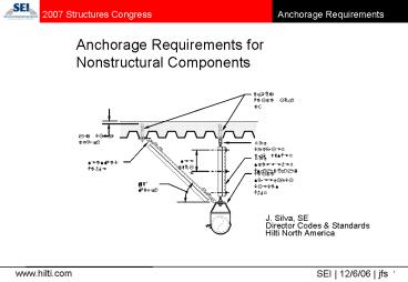
Anchorage Requirements for Nonstructural
Components
5/8 HILTI KB-TZ
1 CLR, TYP.
ROD COUPLER W/ WASHER
ROD STIFFENER HS-158-12
SEE TABLE
SEISMIC HINGE
HILTI SPEEDLOCK CLEVIS HNGR
45? MAX.
J. Silva, SE Director Codes Standards Hilti
North America
2
- Current timeline for California adoption of a
building code based on the 2006 IBC - mid-2007 publish
- 1Q 2008 adopt
- rollout 6 months
3
- Contents
- acceptance criteria and approvals
- IBC provisions for anchorage
- ASCE-7 nonstructural component design
- ACI Appendix D
- design philosophy some suggestions
- Contents
- acceptance criteria and approvals
- IBC provisions for anchorage
- ASCE-7 nonstructural component design
- ACI Appendix D
- design philosophy some suggestions
IWB Stuttgart
4
Document flow for anchor qualification and design
in concrete
IBC Section 1912 Strength Design of Anchors
AC308 Acceptance Criteria for Post-Installed
Adhesive Anchors in Concrete Elements
5
- ICC Evaluation Service
- AC193 (Acceptance Criteria for Mechanical Anchors
in Concrete Elements) - incorporates ACI 355.2, ongoing
corrections/updates to reflect ACI 355 committee
work - includes screw anchors
- AC308 (Acceptance Criteria for Post-Installed
Adhesive Anchors in Concrete Elements) - substantially based on ACI 355.2
- includes necessary modifications to design model
in Appendix D
6
Evaluation Reports based on previous criteria are
being cancelled AC01 reports for mechanical
expansion anchors in concrete were cancelled
effective 1/1/07. (Still ok for masonry.) AC58
reports for adhesive anchors in concrete are
limited to SDC A and B (and only for IBC 2000,
legacy codes) through 2007, and will be cancelled
effective 1/1/08. AC106 reports for screw anchors
in concrete are limited to SDC A and B through
2007, and will be cancelled effective 1/1/08.
Reason The 2003 IBC (Section 1913, ACI 318
Appendix D Section D.3.3.2, ACI 355.2) provided
concise code requirements for post-installed
concrete anchor products used in regions of
moderate and high seismic risk (defined in the
2006 IBC as SDC C, D, E or F). ICC-ES allowed a
three-year time period for expansion and undercut
anchors to comply with the requirements. Since
these anchors must now comply with the code
requirements for use in moderate and high seismic
risk regions, it would not be reasonable to
continue recognition of bonded anchors and screw
anchors in these regions, unless they complied
with similar requirements described in AC193 and
AC308. (ICC-ES 9/15/06 memorandum)
7
Adhesive and screw anchor ESRs in 2007
8
- Contents
- acceptance criteria and approvals
- IBC provisions for anchorage
- ASCE-7 nonstructural component design
- ACI Appendix D
- design philosophy some suggestions
IWB Stuttgart
9
IBC Section 1911 Anchorage to Concrete -
Allowable Stress Design 1911.1 Scope. These
provisions do not apply to anchors installed in
hardened concrete or where load combinations
include earthquake loads or effects.
- Post-installed anchors must be designed using the
provisions of 1912 (Strength Design) - Likewise, anchors (cast-in-place and
post-installed) used to resist earthquake loads
must be designed using the provisions of 1912
10
IBC Section 1912 Anchorage to Concrete - Strength
Design 1912.1 Scope. The provisions of this
section shall govern the strength design of
anchors installed in concrete for purposes of
transmitting structural loads from one connected
element to the other. Headed bolts, headed studs
and hooked (J- or L-) bolts cast in concrete and
expansion anchors and undercut anchors installed
in hardened concrete shall be designed in
accordance with Appendix D of ACI 318 as modified
by Section 1908.1.16, provided they are within
the scope of Appendix D.
11
IBC Section 1912 Anchorage to Concrete - Strength
Design (continued) Exception Where the basic
concrete breakout strength in tension of a single
anchor, Nb, is determined in accordance with
Equation (D-7), the concrete breakout strength
requirements of Section D.4.2.2 shall be
considered satisfied by the design procedures of
Sections D.5.2 and D.6.2 for anchors exceeding 2
inches (51 mm) in diameter or 25 inches (635 mm)
tensile embedment depth.
- Size limits apply to shear!
12
25 inches
1150 mm (45 in.)
slide courtesy of J. Obolt, University of
Stuttgart
13
IBC Section 1912 Anchorage to Concrete - Strength
Design (continued) The strength design of anchors
that are not within the scope of Appendix D of
ACI 318, and as amended above, shall be in
accordance with an approved procedure.
- Allows for the design of adhesive anchors, screw
anchors using acceptance criteria developed by
ICC-ES
14
Seismic design of anchors in concrete under the
2006 IBC
1908.1.16 ACI 318, Section D.3.3. Modify ACI 318,
Sections D.3.3.2 through D.3.3.5, to read as
follows D.3.3.2 In structures assigned to
Seismic Design Category C, D, E or F,
post-installed anchors for use under D.2.3 shall
have passed the Simulated Seismic Tests of ACI
355.2. D.3.3.3 In structures assigned to
Seismic Design Category C, D, E or F, the design
strength of anchors shall be taken as 0.75 ? Nn
and 0.75 ? Vn, where ? is given in D.4.4 or
D.4.5, and Nn and Vn are determined in accordance
with D.4.1. D.3.3.4 In structures assigned to
Seismic Design Category C, D, E or F, anchors
shall be designed to be governed by tensile or
shear strength of a ductile steel element, unless
D.3.3.5 is satisfied. D.3.3.5 Instead of
D.3.3.4, the attachment that the anchor is
connecting to the structure shall be designed so
that the attachment will undergo ductile yielding
at a load level corresponding to anchor forces no
greater than the design strength of anchors
specified in D.3.3.3, or the minimum design
strength of the anchors shall be at least 2.5
times the factored forces transmitted by the
attachment.
15
IBC Section 1908 Modification to ACI
318 1908.1.16 ACI 318, Section D.3.3. Modify ACI
318, Sections D.3.3.2 through D.3.3.5, to read as
follows D.3.3.2 In structures assigned to
Seismic Design Category C, D, E or F,
post-installed anchors for use under D.2.3 shall
have passed the Simulated Seismic Tests of ACI
355.2.
- Defines seismic in terms of Seismic Design
Categories (C and above). - Requires qualification per ACI 355.2
- AC193 and AC308 are based on ACI 355.2
16
IBC Section 1908 Modification to ACI 318
(cont.) D.3.3.3 In structures assigned to
Seismic Design Category C, D, E or F, the design
strength of anchors shall be taken as 0.75 ? Nn
and 0.75 ? Vn, where ? is given in D.4.4 or
D.4.5, and Nn and Vn are determined in accordance
with D.4.1.
17
IBC Section 1908 Modification to ACI 318
(cont.) D.3.3.3 In structures assigned to
Seismic Design Category C, D, E or F, the design
strength of anchors shall be taken as 0.75 ? Nn
and 0.75 ? Vn, where ? is given in D.4.4 or
D.4.5, and Nn and Vn are determined in accordance
with D.4.1.
- This section will be revised in ACI 318-08 to
exclude the steel strength in tension and shear
from the 0.75 factor.
18
IBC Section 1908 Modification to ACI 318
(cont.) D.3.3.4 In structures assigned to
Seismic Design Category C, D, E or F, anchors
shall be designed to be governed by tensile or
shear strength of a ductile steel element, unless
D.3.3.5 is satisfied.
- Ductile design requirement will be made more
difficult by applying 0.75 factor to concrete
failure modes only.
19
IBC Section 1908 Modification to ACI 318
(cont.) D.3.3.5 Instead of D.3.3.4, the
attachment that the anchor is connecting to the
structure shall be designed so that the
attachment will undergo ductile yielding at a
load level corresponding to anchor forces no
greater than the design strength of anchors
specified in D.3.3.3, or the minimum design
strength of the anchors shall be at least 2.5
times the factored forces transmitted by the
attachment.
- This option will appear in ACI 318-08 (but on the
resistance side of the equation)
20
Options for the seismic design of anchorages
21
IBC Section 1908 Modification to ACI 318 (cont.)
- Reduced resistance associated with non-ductile
failure
22
Comparison with old ASD approach
- FS 4 taken on mean resistance (from 5 tests)
App. D
23
- Contents
- acceptance criteria and approvals
- IBC provisions for anchorage
- ASCE-7 nonstructural component design
- ACI Appendix D
- design philosophy some suggestions
IWB Stuttgart
24
Seismic provisions for non-structural components
2006 IBC SECTION 1613 EARTHQUAKE LOADS 1613.1
Scope. Every structure, and portion thereof,
including nonstructural components that are
permanently attached to structures and their
supports and attachments, shall be designed and
constructed to resist the effects of earthquake
motions in accordance with ASCE 7, excluding
Chapter 14 and Appendix 11A. The seismic design
category for a structure is permitted to be
determined in accordance with Section 1613 or
ASCE 7.
25
ASCE 7-05 prescribed forces for nonstructural
components
- 13.4.2 Anchors in Concrete or Masonry Anchors
embedded in concrete or masonry shall be
proportioned to carry the least of the following - 1.3 times the force in the component and its
supports due to the prescribed forces. - The maximum force that can be transferred to the
anchor by the component and its supports. - The value of Rp used in the Section 13.3.1 to
determine the forces in the connected part shall
not exceed 1.5 unless - The component anchorage is designed to be
governed by the strength of a ductile steel
element, or - The design of post-installed anchors in concrete
used for the component anchorage is prequalified
for seismic applications in accordance with ACI
355.2, or - The anchor is designed in accordance with
Section 14.2.2.17.
What was written
26
- 13.4.2 Anchors in Concrete or Masonry Anchors
embedded in concrete or masonry shall be
proportioned to carry the least of the following - 1.3 times the force in the component and its
supports due to the prescribed forces. - The maximum force that can be transferred to the
anchor by the component and its supports. - The value of Rp used in the Section 13.3.1 to
determine the forces in the connected part shall
not exceed 1.5 unless - something else yields before the anchor failsOR
- the anchor is qualified in accordance with ACI
355.2, designed in accordance with ACI 318-05
Appendix D and meets the requirements of IBC
Section 1908.1.16.
What was meant
27
1908.1.16 ACI 318, Section D.3.3. Modify ACI 318,
Sections D.3.3.2 through D.3.3.5 to read as
follows D.3.3.2 In structures assigned to
Seismic Design Category C, D, E or F,
post-installed anchors for use under D.2.3 shall
have passed the Simulated Seismic Tests of ACI
355.2. D.3.3.3 In structures assigned to
Seismic Design Category C, D, E or F, the design
strength of anchors shall be taken as 0.75? Nn
and 0.75? Vn, where ? is given in D.4.4 or D.4.5,
and Nn and Vn are determined in accordance with
D.4.1. D.3.3.4 In structures assigned to
Seismic Design Category C, D, E or F, anchors
shall be designed to be governed by tensile or
shear strength of a ductile steel element, unless
D.3.3.5 is satisfied. D.3.3.5 Instead of
D.3.3.4, the attachment that the anchor is
connecting to the structure shall be designed so
that the attachment will undergo ductile yielding
at a load level corresponding to anchor forces no
greater that the design strength of anchors
specified in D.3.3.3, or the minimum design
strength of the anchors shall be at least 2.5
times the factored forces transmitted by the
attachment.
28
Table 13.6-1 Seismic Coefficients for Mechanical
and Electrical Components
ASCE 7-02 (red)
4.8
2.4
3.5
1.0
3.5
3.6
1.8
2.5
1.0
2.5
1.2
1.5
1.0
1.5
29
assume Ip 1.5, gnd floor
30
1908.1.16 ACI 318, Section D.3.3. Modify ACI 318,
Sections D.3.3.2 through D.3.3.5 to read as
follows D.3.3.2 In structures assigned to
Seismic Design Category C, D, E or F,
post-installed anchors for use under D.2.3 shall
have passed the Simulated Seismic Tests of ACI
355.2. D.3.3.3 In structures assigned to
Seismic Design Category C, D, E or F, the design
strength of anchors shall be taken as 0.75? Nn
and 0.75? Vn, where ? is given in D.4.4 or D.4.5,
and Nn and Vn are determined in accordance with
D.4.1. D.3.3.4 In structures assigned to
Seismic Design Category C, D, E or F, anchors
shall be designed to be governed by tensile or
shear strength of a ductile steel element, unless
D.3.3.5 is satisfied. D.3.3.5 Instead of
D.3.3.4, the attachment that the anchor is
connecting to the structure shall be designed so
that the attachment will undergo ductile yielding
at a load level corresponding to anchor forces no
greater that the design strength of anchors
specified in D.3.3.3, or the minimum design
strength of the anchors shall be at least 2.5
times the factored forces transmitted by the
attachment.
Exception Anchors in concrete designed to
support non-structural components in accordance
with ASCE 7 Section 13.4.2 need not satisfy
Sections D.3.3.4.
Exception Anchors in concrete designed to
support non-structural components in accordance
with ASCE 7 Section 13.4.2 need not satisfy
Sections D.3.3.5.
31
Remember that for the purpose of establishing
seismic design requirements, the contents of a
structure share the same SDC as that determined
for the structure.
Nonstructural building components (e.g.
mechanical equipment, facades) may be exempt from
seismic design requirements depending on the SDC
to which they are assigned.
32
ASCE 7-05 Section 13.1.4
13.1.4 Exemptions. The following nonstructural
components are exempt from the requirements of
this section 1. Architectural components in
Seismic Design Category B other than parapets
supported by bearing walls or shear walls
provided that the component importance factor
(Ip) is equal to 1.0. 2. Mechanical and
electrical components in Seismic Design Category
B. 3. Mechanical and electrical components in
Seismic Design Category C provided that the
component importance factor (Ip) is equal to
1.0. 4. Mechanical and electrical components in
Seismic Design Categories D, E, and F where the
component importance factor (Ip) is equal to 1.0
and either a. flexible connections between the
components and associated ductwork, piping, and
conduit are provided. b. components are mounted
at 4 ft (1.22 m) or less above a floor level and
weigh 400 lb (1780 N) or less. 5. Mechanical and
electrical components in Seismic Design
Categories D, E, and F where the component
importance factor (Ip) is equal to 1.0
and a. flexible connections between the
components and associated ductwork, piping, and
conduit are provided. b. the components weigh
20 lb (95N) or less or, for distribution systems,
weighing 5 lb/ft (7 N/m) or less.
33
- Contents
- acceptance criteria and approvals
- IBC provisions for anchorage
- ASCE-7 nonstructural component design
- ACI Appendix D
- design philosophy some suggestions
IWB Stuttgart
34
ACI 318-05 Appendix D(briefly)
IWB Stuttgart
35
Anchor Failure Modes - Tension
- 1. concrete breakout
- 2. bond failure/pullout
3. steel rupture 4. edge breakout 5. concrete
splitting
36
Interface adhesive / concrete
Interface steel / adhesive
Interface adh./conc. and steel / adh.
steel
concrete cone
Adhesive anchor failure modes observed in tests
(after Cook, et al. (1998))
37
N?NU
NgtNU
IWB Stuttgart
Concrete cone failure Test and numerical
simulation (IWB Stuttgart)
38
2 hef
Derivation of old 45 degree cone equation (ACI
349-85)
hef
45 degrees
old ACI 349
39
load
displacement
40
Derivation of CC equation for concrete breakout
of a single anchor in tension
fracture mechanics correction for large strain
gradient
35 mean failure load for most post-installed
expansion anchors (lb, in. units)
40 mean failure load for headed studs and most
undercut anchors
for the prediction of the capacity associated
with concrete breakout, the CC method is
remarkably accurate over a wide range of
embedments
41
projected area of a failure surface
approximated as the base of a rectilinear
geometrical figure that results from projecting
the failure surface outward 1.5hef from the
centerlines of the anchor, or in the case of an
anchor group, from a line through a row of
adjacent anchors. ANc may not exceed nANco, where
ANco is the projected area of a single anchor
remote from edges.
3hef
3hef
hef
ACI 318-05 Appendix D
42
ca1
ca1
s1
ANc (ca1 1.5hef) (2 x 1.5hef) if ca1 lt 1.5hef
s2
ca2
ANc (ca1 s1 1.5hef) (ca2 s2 1.5hef) if
ca1 and ca2 lt 1.5hef and s1 and s2 lt 3hef
ca1
s1
ANc (ca1 s1 1.5hef) (2 x 1.5hef) if ca1 lt
1.5he and s1 lt 3hef
examples for determining ANc
ACI 318-05 Appendix D
43
Load (kN)
uncracked concrete cracked concrete ?w 0.3
mm ßw ? 34 N/mm2
? 25 reduction
CIP studs Load-displacement curves for 12 mm
headed studs set in uncracked concrete and in 0.3
mm line cracks
Headed studs dia. 12 mm hef 80 mm
Furche, Dieterle 1996
Displacement (mm)
44
(No Transcript)
45
(No Transcript)
46
Example Equipment anchorage
1,200 lb
500 lb
housekeeping pad f'c 4,000 psi
125 mm (4.92 in.)
4 in.
Design the anchorage for a telecom rack on a
housekeeping pad for the factored tension and
shear loads as shown. The anchor is a
post-installed undercut anchor with an embedment
depth hef 5 in. The edge distance is 4 in. The
concrete strength is 4,000 psi. Design data for
the post-installed anchor is given as shown at
left. The anchor has been qualified per ACI 355.2
for earthquake loading.
47
Code Reference
Calculations and Discussion
ANc
1.5hef
1.5hef
1.5hef
c
Plan
48
Code Reference
Calculations and Discussion
49
Code Reference
Calculations and Discussion
1.5ca1
1.5ca1
1.5ca1
h
AVc
ca1
1.5ca1
1.5ca1
Plan
Elevation
50
Code Reference
Calculations and Discussion
51
Code Reference
Calculations and Discussion
52
Code Reference
Calculations and Discussion
53
Code Reference
Calculations and Discussion
1.0
0.56
0.2
0.2
0.55
1.0
Tri-linear interaction curve
54
- Contents
- acceptance criteria and approvals
- IBC provisions for anchorage
- ASCE-7 nonstructural component design
- ACI Appendix D
- design philosophy some suggestions
IWB Stuttgart
55
Rationale for strength reduction factors
5 fractile of resistance to account for normal
scatter in concrete failure modes
overstrength for non-ductile failure
variations in material strength, design, etc.
uncertainties associated with resistance in EQ
56
Options for the seismic design of anchorages
57
T
b
a
Prying Force Q
Bolt Force Bc
58
Options for the seismic design of anchorages
59
Crushing strength of sill plate
Edge distance too small to satisfy ductility
criteria
60
Ductility conditions
I
II
SDC C or above?
Cond. (I) and (II) satisfied?
YES
NO
NO
NO
design as non-ductile
?
?
YES
YES
YES
NO
design as ductile
NO
Cond. (I) satisfied?
design as non-ductile
NO
YES
Cond. (II) satisfied?
NO
design as non-ductile
?
design as ductile
YES
YES
design as non-ductile
design as ductile
61
non-ductile design
Anchor design for attachment yield?
NO
ductile design
YES
Design attachment for factored loads. In addition
62
John F. Silva, SE Director, Codes
Standards Hilti North America
Recommended
CrystalGraphics Presentations


