
Packet Switch: Intersection where Traffic Flows Meet - PowerPoint PPT Presentation
1 / 25
Title:
Packet Switch: Intersection where Traffic Flows Meet
Description:
Interconnection Fabric. Transfer packets between line cards. Egress Line Cards ... self-routing multi-stage fabrics. Virtual connections setup across network ... – PowerPoint PPT presentation
Number of Views:78
Avg rating:3.0/5.0
Title: Packet Switch: Intersection where Traffic Flows Meet
1
Packet Switch Intersection where Traffic Flows
Meet
1
1
2
2
? ? ?
? ? ?
N
N
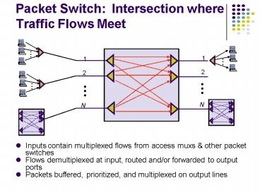
- Inputs contain multiplexed flows from access muxs
other packet switches - Flows demultiplexed at input, routed and/or
forwarded to output ports - Packets buffered, prioritized, and multiplexed on
output lines
2
Generic Packet Switch
- Unfolded View of Switch
- Ingress Line Cards
- Header processing
- Demultiplexing
- Routing in large switches
- Controller
- Routing in small switches
- Signalling resource allocation
- Interconnection Fabric
- Transfer packets between line cards
- Egress Line Cards
- Scheduling priority
- Multiplexing
3
Shared Memory Packet Switch
Output Buffering
Ingress Processing
Connection Control
1
1
Queue Control
2
2
3
3
Shared Memory
N
N
Small switches can be built by reading/writing
into shared memory
4
Crossbar Switches
(b) Output buffering
(a) Input buffering
Inputs
Inputs
3
1
1
2
3
8
2
3
3
N
N
1
2
3
N
1
2
3
N
Outputs
Outputs
- Large switches built from crossbar multistage
space switches - Requires centralized controller/scheduler (who
sends to whom when) - Can buffer at input, output, or both (performance
vs complexity)
5
Asynchronous Tranfer Mode (ATM)
- Packet multiplexing and switching
- Fixed-length packets cells
- Connection-oriented
- Rich Quality of Service support
- Conceived as end-to-end
- Supporting wide range of services
- Real time voice and video
- Circuit emulation for digital transport
- Data traffic with bandwidth guarantees
6
ATM Networking
Packet
Voice
Video
Packet
Voice
Video
ATM Adaptation Layer
ATM Adaptation Layer
ATM Network
- End-to-end information transport using cells
- 53-byte cell provide low delay and fine
multiplexing granularity
- Support for many services through ATM Adaptation
Layer
7
ATM Attributes of TDM Packet Switching
- Packet structure gives flexibility efficiency
- Synchronous slot transmission gives high speed
density
Packet Header
8
TDM vs. Packet Multiplexing
?
?
?
In mid-1980s, packet processing mainly in
software and hence slow By late 1990s, very
high speed packet processing possible
9
ATM Switching
Switch carries out table translation and routing
ATM switches can be implemented using shared
memory, shared backplanes, or self-routing
multi-stage fabrics
10
ATM Virtual Connections
- Virtual connections setup across network
- Connections identified by locally-defined tags
- ATM Header contains virtual connection
information - 8-bit Virtual Path Identifier
- 16-bit Virtual Channel Identifier
- Powerful traffic grooming capabilities
- Multiple VCs can be bundled within a VP
- Similar to tributaries with SONET, except
variable bit rates possible
Virtual paths
Physical link
Virtual channels
11
VPI/VCI switching multiplexing
- Connections a,b,c bundled into VP at switch 1
- Crossconnect switches VP without looking at VCIs
- VP unbundled at switch 2 VC switching
thereafter - VPI/VCI structure allows creation virtual networks
12
MPLS ATM
- ATM initially touted as more scalable than packet
switching - ATM envisioned speeds of 150-600 Mbps
- Advances in optical transmission proved ATM to be
the less scalable _at_ 10 Gbps - Segmentation reassembly of messages streams
into 48-byte cell payloads difficult
inefficient - Header must be processed every 53 bytes vs. 500
bytes on average for packets - Delay due to 1250 byte packet at 10 Gbps 1
msec delay due to 53 byte cell _at_ 150 Mbps 3
msec - MPLS (Chapter 10) uses tags to transfer packets
across virtual circuits in Internet
13
Multicasting
- Source S sends packets to multicast group G1
14
Multicast Routing
- Multicast routing useful when a source wants to
transmits its packets to several destinations
simultaneously - Relying on unicast routing by transmitting each
copy of packet separately works, but can be very
inefficient if number of destination is large - Typical applications is multi-party conferencing
over the Internet - Example Multicast Backbone (MBONE) uses reverse
path multicasting
15
Reverse-Path Broadcasting (RPB)
- Fact Set of shortest paths to the source node S
forms a tree that spans the network - Approach Follow paths in reverse direction
- Assume each router knows current shortest path to
S - Upon receipt of a multicast packet, router
records the packets source address and the port
it arrives on - If shortest path to source is through same port
(parent port), router forwards the packet to
all other ports - Else, drops the packet
- Loops are suppressed each packet forwarded a
router exactly once - Implicitly assume shortest path to source S is
same as shortest path from source - If paths asymmetric, need to use link state info
to compute shortest paths from S
16
Example Shortest Paths from S
- Spanning tree of shortest paths to node S and
parent ports are shown in blue
17
Example S sends a packet
?
G1
G1
1
2
7
3
2
4
2
3
4
2
1
5
1
2
5
G1
3
3
8
4
2
1
1
4
S
G1
1
3
5
4
2
2
4
6
3
1
3
2
1
1
G2
3
4
3
G3
G3
- S sends a packet to node 1
- Node 1 forwards to all ports, except parent port
18
Example Hop 1 nodes broadcast
?
?
G1
G1
1
2
7
3
2
4
2
3
4
2
1
5
1
?
2
5
G1
3
3
8
4
2
1
?
1
4
S
G1
1
3
5
4
2
2
4
6
3
1
3
2
1
1
G2
3
4
3
G3
G3
- Nodes 2, 3, 4, and 5 broadcast, except on parent
ports - All nodes, not only G1, receive packets
19
Example Broadcast continues
G1
G1
1
2
7
3
2
4
2
3
4
2
1
5
1
2
5
G1
3
3
8
4
2
1
1
4
S
G1
1
3
5
4
2
2
4
6
3
1
3
2
1
1
G2
3
4
3
G3
G3
- Truncated RPB (TRPB) Leaf routers do not
broadcast if none of its attached hosts belong to
packets multicast group
20
Internet Group Management Protocol (IGMP)
- Internet Group Management Protocol
- Host can join a multicast group by sending an
IGMP message to its router - Each multicast router periodically sends an IGMP
query message to check whether there are hosts
belonging to multicast groups - Hosts respond with list of multicast groups they
belong to - Hosts randomize response time cancel response if
other hosts reply with same membership - Routers determine which multicast groups are
associated with a certain port - Routers only forward packets on ports that have
hosts belonging to the multicast group
21
Reverse-Path Multicasting (RPM)
- Reverse Path Multicasting (RPM) relies on IGMP to
identify multicast group membership - The first packet to a given (source, group), i.e.
(S,G) is transmitted to all leaf routers using
TRPB - Each leaf router that has no hosts that belong to
this group on any of its ports, sends a prune
message to its upstream router to stop sending
packets to (S, G) - Upstream routers that receive prune messages from
all their downstream routers, send prune messages
upstream - Prune entries in each router have finite lifetime
- If a host requests to join a group, routers can
cancel previous pruning with a graft message
22
Example Pruning for G1
G1
G1
1
2
7
3
2
4
2
3
4
2
1
5
1
2
5
G1
3
3
8
4
2
1
1
4
S
G1
1
3
5
4
2
2
4
6
3
1
3
2
1
1
G2
3
4
3
G3
G3
- Routers 3, 4, and 6 send prune messages upstream
23
Example RPM Multicast Tree
G1
G1
1
2
7
3
2
4
2
3
4
2
1
5
1
2
5
G1
3
3
8
4
2
1
1
4
S
G1
1
3
5
4
2
2
4
6
3
1
3
2
1
1
G2
3
4
3
G3
G3
- RPM multicast tree after pruning
24
Example Graft from Router 6
G1
G1
1
2
7
3
2
4
2
3
4
2
1
5
1
2
5
G1
3
3
8
4
2
1
1
4
S
G1
1
3
Graft
5
4
2
2
4
6
3
1
3
2
1
1
G1
3
4
3
G3
G3
- Graft message flows upstream to router 1
25
Example RPM Tree after Graft
G1
G1
1
2
7
3
2
4
2
3
4
2
1
5
1
2
5
G1
3
3
8
4
2
1
1
4
S
G1
1
3
5
4
2
2
4
6
3
1
3
2
1
1
G1
3
4
3
G3
G3
Recommended
CrystalGraphics Presentations


