
Chapter 45: Dislocations and Slip - PowerPoint PPT Presentation
1 / 33
Title:
Chapter 45: Dislocations and Slip
Description:
Slip plane and Directions (Burger's vectors) ... planes in the direction of ... does not lie in either of the two slip planes, but does lie in n = b x u= (001) ... – PowerPoint PPT presentation
Number of Views:2092
Avg rating:3.0/5.0
Title: Chapter 45: Dislocations and Slip
1
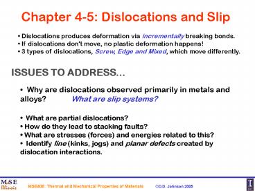
Chapter 4-5 Dislocations and Slip
- Dislocations produces deformation via
incrementally breaking bonds. - If dislocations don't move, no plastic
deformation happens! - 3 types of dislocations, Screw, Edge and Mixed,
which move differently.
ISSUES TO ADDRESS...
Why are dislocations observed primarily in
metals and alloys? What are slip systems?
- What are partial dislocations?
- How do they lead to stacking faults?
- What are stresses (forces) and energies related
to this? - Identify line (kinks, jogs) and planar defects
created by dislocation interactions.
2
Dislocations Materials Classes
Metals Disl. motion easier.
-non-directional bonding -slip in
close-packed directions.
FCC 111 planes in lt110gt dirs. BCC 110,
211 and 321 in lt111gt dirs., HCP 0001,
others in lt1120gt dirs.
electron cloud
ion cores
Covalent Ceramics (Si, diamond) Motion
hard. -directional (angular) bonding
No!
Ionic Ceramics (NaCl) Motion hard.
-avoid and -- neighbors. fcc -based NaCl
slip 110 planes with lt110gt dirs., rather than
111) planes.
possible
3
Slip plane and Directions (Burgers vectors)
- Each crystal structure (e.g., fcc, bcc, and hcp)
has different allowed slip planes, occurring at
specific angles to applied stress, and different
slip directions, occurring at other angles. - Shear stress (not normal stress) is what causes
planar slip to occur. - Active slip plane is typically the most
CLOSE-PACKED Planes. - Active slip direction is the most CLOSE-PACKED
Directions.
FCC Slip plane and Directions
(111) planes in the direction of
Slip systems 4 x 3 12
4
BCC Slip Planes and Directions
Principal slip system, but other closed-packed
directions
110 planes in the direction of
?Fe, Mo, W, ? brass
Slip systems 6 x 2 12
211 planes in the direction of
?Fe, Mo, W, Na
Slip systems 12 x 1 12
321 planes in the direction of
?Fe, K
Slip systems 24 x 1 24
5
HCP Slip Planes and Directions
Principal slip system can depend on c/a and
relative orientation of load to slip planes
hcp Zinc single crystal
0001 planes in the direction of
Slip systems 1 x 3 3
c/a 1.6333 (ideal)
Cd, Zn, Mg, Ti, Be
Adapted from Fig. 7.9, Callister 6e.
planes in the direction of
Slip systems 3 x 1 3
Ti
planes in the direction of
Adapted from Fig. 7.8, Callister 6e.
Slip systems 6 x 1 6
c/a 1.6333 (ideal)
Mg, Ti
6
Energy of Screw Dislocation
Only non-zero displacements for screw.
u3 gives the only non-zero strains
Screw
Roll open cylinder, shear displacement is
Energy/Volume for (elastic) distortion
and
For infinitesimal region,
or
Energy per unit length of screw dislocation
(integrating from r0 to r)
Roughly, due to r dependence
Elasticity theory breaks down for r05b so core
energy is ignored here.
7
Energy of Edge Dislocations
For idealized edge component, one entire plane
has been pushed into the other planes above the
glide plane but not below (tensile compressive
stresses). Hence, there is Poisson Effect along
length of line, which yields a (1-v) in
denominator for strain.
Idealized Edge
compression
For many metals, v 1/3, so
Elasticity theory breaks down for r05b so core
energy is ignored here.
8
Energy and Forces of Edges
Idealized
Roughly, your expectation should be (as found
from intuition)
b
Energy before 2Gb2 Energy after Gbtot2 0
Should attract
b
b0
b
b
Energy before 2Gb2 Energy after Gbtot2
G(2b)2 4Gb2
Should repel
b2
9
Energy of Mixed Dislocation
Energy has components from Screw and Edge.
Energy has component from both types
As in download notes
b
Edge
Screw
Screw
mixed
u
b
Combining (Screw, Mixed, Edge)
b
Edge
10
FCC Partial Dislocations and Stacking Faults
(111) fcc plane
Partial Dislocations b b1 b2
b1
b2
b
b2y
b1y
b2x
b1x
b1y and b2y are attractive screw segments b1x
and b2x are repulsive edge segments
If energy is favorable, Gb2 gt Gb12 Gb22, then
partial dislocation form. (Show Ga2/2 gt Ga2/3)
Energies of Full and Partials are
Favorable for partials to form, i.e. dislocation
disassociate.
Dislocations may be sessile if not on the correct
slip plane.
due to ABC stacking
Here partials form, edge repulsion wins out,
which creates stacking faulted region in between.
11
FCC Partial Dislocations and Stacking Faults
(111) fcc plane
Partial Dislocations b b1 b2
Motion of partials
In FCC, due to ABC stacking, if partials
form, edge repulsion wins out, which creates
stacking faulted region in between. Green
Partials Separate.
b
Separation of partials
Stacking Faults are defects that cost
energy Energy balance between separating partials
to lower elastic energy and creation of more SF.
Partial dislocations move apart. As they move
apart leave hcp SF ribbon. ABC 3 layers AB
2 layers ABCABC converts to ABABAB
12
Separation of Partials Stacking Fault
Here partials are favorable, Gb2 gt Gb12 Gb22,
since Ga2/2 gt Ga2/3. Edge bedge are b1x
b2x, so b2edge a2/8 Screw b2screw (b
b1)2 a2/24
u for edge
(anti-)parallel screws (attract) repel.
The SF region is created at the expense of moving
partial apart Energy of SF (J/m) ?SF r, so can
equate F (N/m) ?SF (J/m2) High SFE low
separation, low SFE large separation in TEM.
13
Stacking Faults and Energy
Partial dislocation repel and leave stacking
faults
Stacking Faults are defects that cost
energy Energy balance between separating partials
to lower elastic energy and creation of more SF.
For ideal case
In TEM, you see contrast between faulted and
unfaulted regions, hence, you can measure dSF and
get SFE.
14
Dislocation Kinks piecewise movement of line
Glide moves one b locally until entire
dislocation has moved according to forces
(applied internal).
- dislocation minimizes length (costs E/L) to
minimize strain energy. - dislocations curve to avoid obstacles to motion
along slip plane.
15
Dislocation Kinks piecewise movement of line
Dislocation moves by piecewise kinks and running
them the length of dislocation. Such motion is
temperature dependent (due to nucleation of
kinks) such as in BCC.
In BCC, for example, corrugated surface
represents the energy for the moving
dislocations, which tend to lie in the minima.
After a double kink pair (blue) nucleates,the
kinks migrate (black) so that the dislocation
moves from one minimum to another.
Kink motion
Dislocation motion
VKink gt VDisl
Perspective, D. Chrzan, Science 310 (2005)
16
Dislocation Velocities vs Applied Shear
LiF crystal
For LiF edges segments move 50x faster than
screw segments!
Fe-3.25Si crystal
17
Full (Mixed) Dislocation Recombination Lormer
Locks
e.g., Fig. 4.39 MC
(MIXED) full dislocation reaction b b1 b2
Check slip planes?
motion
n(001)
Burgers vector, b? (See figure above in
cube) Favorable to recombine? Yes, Gb12
Gb22 gt Gb2 Slip Plane? does not
lie in either of the two slip planes, but does
lie in n b x u (001). Glissile or Sessile?
Sessile, not 111 fcc slip plane
motion
Mixed dislocations us are all parallel to
intersection, and bs are not ? to us.
- Unless lock (sessile dislocation) is removed,
dislocation on same plane cannot move past. - Going back b gt b1 b2 would allow other
dislocation to glide again.
18
Shockley Partial Dislocations Recombination
Locks
Partial dislocations reaction b bp1 bp2
e.g., Fig. 4.39 MC
motion
n
Burgers vector? Leading partials
combine Favorable to recombine? Check Gb12
Gb22 gt Gb2 Line Direction? Slip
Plane? Glissile or Sessile? Sessile, not 111
fcc slip plane
motion
Lormer-Cottrell lock. But if full bs combine, it
is Lormer lock.
- Unless lock (sessile dislocation) is removed,
dislocation on same plane cannot move past. - other possible combinations give
19
Edge-Edge Interactions creates edge jogs
Dislocations each acquire a jog equal to the
component of the other dislocations Burgers
vector that is normal to its own slip
plane. Energy cost of jog Gb2/2 (Energy/length)
x b (length of jog) Gb3/2
This dislocation got a jog in direction of b1e.
Dislocation 1 got a jog in direction of b2e of
the other dislocation thus, it got longer. Extra
atoms in half-plane increases length.
What happens when dislocations are extended, i.e.
composed of two trailing partials?
20
Screw-Edge Dislocation Interactions creates edge
jogs
Time snap shots
Edge jog is in direction of bs. Jogs slow motion
of dislocation.
Energy cost of jog is Gb3/2
Why does screw also have jog?
21
Screw-Edge Dislocation Interactions creates edge
jogs
Edge jog is in direction of bs. Jogs slow motion
of dislocation.
Screw jog is in direction of be. Why is there a
jog in screw?
22
Screw-Screw Dislocation Interactions creates
edge jogs
Energy cost of jog Gb3/2
Jogs slow motion of dislocation. In screw-screw
case, jog has to move via CLIMB, or generate a
row VACANCIES or INTERSTITIALS. Climb is
non-conservative, and point-defects costs more
energy.
23
Multiplication of Dislocations
- To account for large plastic strain that can be
produced in crystals, it is necessary to have
regenerative multiplication of dislocations. Of
course, there are many variants that lead to many
effects. - Two important mechanisms for this are
- Frank-Read sources and multiple cross
glide
Marked pts could be from cross slip
Fig. 3.10 Cross slip of single crystal of
Fe-3.25Si
From Hall and Bacon 4th Ed
24
Dislocations Generation single-ended Frank-Read
source
Single-ended Frank-Read source leads to
regenerative multiplication. This mechanisms can
be attained from a superjog, where an extended
line is out of the slip plane and thus sessile.
- Segment BC is edge anchored at one end. (a)
- Moves by rotating. (b)
- Each revolution around B displaces the crystal
above slip plane by b, so n revolutions gives nb
slip. - Spiraling around B increases line length.
For superjogs, see book and Gilman and Johnston,
Solid State Physics 13, 147 (1962).
25
Dislocation Generation Frank-Read
Source Aftereffects of dislocation-dislocation
interaction
Shear bowing of line
- applied
- shear stress
Small jog
?
Unstable position loop expands
r?
L
?/2
r
T
?/2
Tsin?/2
Tsin?/2
Line Tension (E/L) 2T sin?/2 T? ?Gb2/2
opposes bowing via shear ? F/L bowing arc
?b r? So, ?b r? ?Gb2/2 ? Gb/2r Radius
of curvature r smallest for semicircular arc of
r L/2. Larger L easier to deform. ?max Gb/L
What type of dislocations? What can happen?
Screws annihilate
Generated a dislocation in place of old one,
which is now a loop. (Shaded area has 1 unit of
slip.) Larger density. Back stresses hinder
motions.
Shape due to Si directional bonding
26
Dislocation Generation Frank-Read Source via
Cross Slip
What type of dislocation is in (a)?
- applied shear stress can be parallel and
perpendicular to b.
Looks like two pints on (111) plane, as in Si
case
Bowing of cross slipped dislocation line is
similar to jogged dislocations.
27
Prismatic Dislocation Loops
Prismatic Loops in dislocation-free AgCl with
small glass sphere that induces strain fields due
to differential contraction during cooling.
Glass sphere
Prismatic loops
From Hall and Bacon 4th Ed
28
Prismatic Dislocation Loops Dislocation-Particle
Interactions
Prismatic Loops also can form during dislocation
motion on slip plane containing precipitate or
particle.
Prismatic loops
From Hall and Bacon 4th Ed
29
Superlattice Dislocations Create APBSF
Order alloys have larger Burger vectors and more
defects that can form due to dislocation glide.
- Without partials, APB but no SF.
- With partials, SF and APB
anti-phase boundary
30
Superlattice Dislocations Create APBSF
L12 or Cu3Au cubic structure
- slip by one fcc Burgers vector creates an
APB(111). - second dislocation creates perfect L12 again.
- unlike fcc, (001) slip is observed in L12.
- (001) slip creates APB(001).
is no longer a Burgers vector
is a Burgers vector due to symmetry of cell
For oxides, where interstitials are occupied by
metals and lattice (like hcp) is occupied by
oxygen, e.g. Al2O3, the Burgers vector is also
larger.
L12 (100) plane
31
Dislocation Glide in Silicon on (111)
Projection of diamond-cubic lattice
Dangling bonds can arise which lead to gap states.
If no reconstruction, then dangling sp3 bonds
would leave deep levels
If reconstructed to get pairwise bonding, then no
dangling sp3 bonds would leave deep levels
32
Epitaxial Misfit Dislocations
Interfacial misfit dislocation due to lattice
mismatch of A on B. There are actually no
dislocations.
Misfit disl.
From Hall and Bacon 4th Ed
33
Summary
- Dislocations (line defects) give rise to
complicated interactions in a crystal. - Dislocation multiplication is responsible for
the very large increases in YS. - Dislocation-dislocation interactions, or
dislocations interacting with other defects, lead
to higher stresses required to move the
dislocations further (work-hardening). For
example, dislocation pile-up, jogs, trasnfer
across grain boundaries, etc., all contribute to
YS increases. - Dislocations interacting with anything lead to
other defects (point, planar, volumetric). - Consequences are found in the allowed slip and
strengthening of materials. - Be familiar/conversant with how dislocations
interact and the consequences. - Are these consequences able to be mathematically
described?
Recommended
CrystalGraphics Presentations


