
Robocup Team Reviews Carnegie Mellon University - PowerPoint PPT Presentation
1 / 27
Title:
Robocup Team Reviews Carnegie Mellon University
Description:
Robocup Team Reviews. Carnegie Mellon University. CSE398/498. 25 Feb 05. Administration ... Advantage: Less sensitive to errors in camera orientation ... – PowerPoint PPT presentation
Number of Views:64
Avg rating:3.0/5.0
Title: Robocup Team Reviews Carnegie Mellon University
1
Robocup Team ReviewsCarnegie Mellon University
CSE398/498 25 Feb 05
2
Administration
- Next team challenge is next Wednesday at 11AM in
PL450 - Field Status
- Travel Dates (We WILL still have labs)
- Mar 14-16 (M-W)
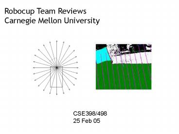
- Mar 21-23 (M-W)
- Apr 18-22 (M-F)
3
References
- CMPack-02 CMUs Legged Robot Soccer Team,
M. Veloso et al - Visual Sonar Fast Obstacle Avoidance Using
Monocular Vision, S. Lenser and M. Veloso, IROS
2003, Las Vegas, USA
4
CMU High Level Vision CMVision
http//www-2.cs.cmu.edu/tekkotsu/Vision.html
5
High Level Vision Ball Detection
- Each ball detection generator receives a list of
the 10 largest (in this case) pink regions
detected in the image - The region with the greatest confidence level
is returned as a ball (maybe) - Confidence threshold specified in tekkotsu.cfg
6
Ball Detection Confidence Calculation
- Constraint filters
- Tilt angle (lt5o above robot head)
- Region size (height 3 pixels, width 3 pixels,
area 7 pixels) - Fringe effects (red uniform on yellow goal)
- Proximity constraints
- Real value filters
- Aspect ratio of the bounding box (BB)
- Pixel area vs. BB area
- Divergence in angle between position calculations
- Confidence calculated from the product of real
value filters - Confidence scaled based upon the number of pixels
to prevent rejection of very close balls
7
Ball Location Calculation
- Two methods used to estimate the relative
position of the ball - Both rely on using coordinate transformations to
determine the position of the camera/ball - Method 1
Once you have D, how would you get the relative
ball position?
8
Ball Location Calculation
- Two methods used to estimate the relative
position of the ball - Both rely on using coordinate transformations to
determine the position of the camera/ball - Method 2
h
D
9
Location Method Comparisons
- Method 1
- Advantage Less sensitive to errors in camera
orientation - Disadvantage Assumes that the entire ball is
visible - Method 2
- Advantage Less sensitive to ball occlusions or
when the ball is at the edge of the picture frame - Disadvantage Noise can cause significant errors
at longer distances
10
High Level Vision Marker Detection
- Marker detection will (probably) be your basis
for robot localization as these serve as
landmarks for position estimation - Need to correctly associate pairs of segmented
regions with the correct landmarks
www.robocup.org
11
Marker Detection Confidence Calculation
- Detection
- Consider all pairs of pink and yellow/cyan out of
the 10 largest regions of each color - The most confident marker readings are used for
localization - Real value filters for confidence calculation
- Angular separation of the two regions
- Relative size of the marker region pair (they
should be roughly equal) - Relative size of each region relative to the
square of the distance between them - Location Calculation
- Take the average of the rays to each region to
form the landmark plane - Use a priori knowledge of landmark size to
estimate position
12
High Level Vision Goal Detection
- Goal detection based upon corner detection to
estimate its position - Goal is represented as three objects
- Left edge
- Right edge
- Central object
- The central object is for behaviors requiring
rough estimates - The edges are for localization and aiming
www.robocup.org
13
Central Goal Object
- Relies on the aspect ratio of the goal and the
goals proximity to the field - Angle to the goal is calculated from the centroid
- Distance to the goal is estimated using its
height - The bearing angle subtended by the goal is also
calculated
14
Corner Detection for Edges
- Start at the centroid of the goal region, and
proceed in the Z direction (world frame) until
no more goal pixels are found (point a) - From the midpoint (no occlusion) between point a
and the centroid, search in the /- Y directions
(again world frame) to form a bounding
rectangle (blue box) - Refine with a local search to ensure all
corners are goal pixels (pink vertices)
http//www-2.cs.cmu.edu/coral-downloads/legged/pa
pers/cmpack_2002_teamdesc.pdf
15
Corner Detection (contd)
- Refine each corner estimate using a gradient
ascent approach - When no further improvement can be achieved,
terminate
http//www-2.cs.cmu.edu/coral-downloads/legged/pa
pers/cmpack_2002_teamdesc.pdf
16
Goal Edge Confidence Calculation
- Constraint filters
- Width Height of the goal
- Goal aspect ratio
- Proximity to the field (green pixels beneath the
goal) - Real value filters
- Goal orientation
- Location Calculation
- Use the height of the goal and the corners to
estimate the distance to the goal
17
Robot Detection
- Relies upon color segmentation
- Need to associate multiple regions from multiple
dogs to multiple regions on individual dogs - Again, this is based primarily on heuristics
- Keep regions separate when there is a lot of
green between them or when they are far apart
18
Visual Sonar
- Based entirely upon color segmentation
- The main idea
- There are only a handful of colors on the field
- Each color can be associated with one or more
objects - green -gt field
- orange -gt ball
- white -gt robot or line
- red or blue -gt robot
- cyan or yellow -gt goal
http//www-2.cs.cmu.edu/coral-downloads/legged/pa
pers/cmpack_2002_teamdesc.pdf
19
Visual Sonar (contd)
- Based entirely upon color segmentation
- The main idea
- Discretize the image by azimuth angle
- Search in the image from low elevation angle to
high for each azimuth angle - When you hit an interesting color (something not
green), evaluate it - You can infer the distance to an object for a
given azimuth angle from the elevation angle and
the robot geometry
http//www-2.cs.cmu.edu/coral-downloads/legged/pa
pers/cmpack_2002_teamdesc.pdf
20
Visual Sonar (contd)
- By panning head you can generate a 180o range
map of the field - Subtleties
- Identifying tape
- Identifying other robots???
- Advantages over IRs
- Video Link
http//www-2.cs.cmu.edu/coral-downloads/legged/pa
pers/cmpack_2002_teamdesc.pdf
21
A Similar Approach
- Based entirely upon edge segmentation
- The main idea
- All edges are obstacle
- All obstacle must be sitting on the ground
- Search in the image from low elevation angle to
high for each bearing angle - When you hit an edge, you can infer the distance
to an obstacle for a given bearing angle from the
elevation angle
22
Why Does this Work?
- Recall that edges correspond to large
discontinuities in image intensity - While the carpet has significant texture, this
pales in comparison with the white lines and
green carpet (or white Aibos and green carpet)
23
Why Does this Work? (contd)
- Lets look at a lab example
- OK, that did not work so great because we still
have a lot of spurious edges from the carpet that
are NOT obstacles - Q How can I get rid of these?
- A Treat these edges as noise and filter them.
- After applying a 2D gaussian smoothing filter to
the image we obtain
24
Position Updates
- Position updates are obtained using the field
markers and the goal edges - Both the bearing and the distance are estimated
to each field marker. - To estimate the pose analytically, the robot
needs to view 2 landmarks simultaneously - CMU uses a probabilistic approach that can merge
individual measurement updates over time to
estimate the pose of the Aibo - We will discuss this in more detail later in the
course
25
The Main Idea
- Recall our example from the last class
- Lets say instead of having 2 sensors/sensor
model, we have a sensing and a motion model - We can combine estimate from our sensors and our
motion over time to obtain a very good estimate
of our position - One slight hiccup
26
The Kidnapped Robot Problem
- If you are going to use such probabilistic
approaches you will need to account for this in
your sensing/motion model
27
Summary
- We reviewed much of the sensing estimation
techniques used by the recent CMU robocup teams - Complete reliance on the vision system
primarily color segmentation - Newer approaches also rely heavily on line
segmentation we may not get to this point - There is a lot of science in the process
- There are a lot of heuristics in the process.
There work well on the Aibo field, but not in a
less constrained environment - Approaches are similar to what many other teams
are using - Solutions are often not pretty - often the way
things are done in the real world
Recommended
CrystalGraphics Presentations


