CTC 261 Culvert Basics - PowerPoint PPT Presentation
Title:
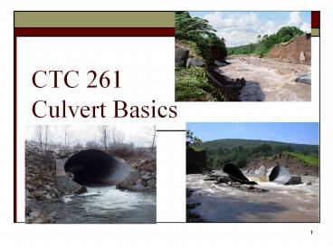
CTC 261 Culvert Basics
Description:
Slope Resistance Roadway Data Cross Section Profile Culvert Length Maps Field Surveys Roadway Plans * Data Requirements Design Headwater Critical pts ... – PowerPoint PPT presentation
Number of Views:196
Avg rating:3.0/5.0
Title: CTC 261 Culvert Basics
1
CTC 261 Culvert Basics
2
Objectives
- Students should have the ability to
- Describe the different materials used for
culverts - Describe the two types of hydraulic control
- Determine the headwater depth for inlet control
3
Hydraulic Design of Highway Culverts
- USDOT/FHWA
- HDS 5 (highway design series 5)
- PDF available at
- http//isddc.dot.gov/OLPFiles/FHWA/012545.pdf
- Most of the images in this powerpoint
presentation were taken from HDS 5
4
Culvert
- Hydraulically short conduit which conveys stream
flow through a roadway embankment or past some
other type of flow obstruction
5
Culvert Design
- Conduit placed under a road to carry water from
one side to the other - Designed to pass a design flow w/o overtopping
the road
6
Culvert Flow
- Complex
- Pressure flow
- Open channel flow
- Combination
- Variables
- Slope
- Pipe Diameter, Length and Roughness
- Entrance Design
- Exit Design
7
Culvert Shapes
8
Culvert Materials
9
Culvert Materials-other
- Corrugated Aluminum
- Plastic
- Polyethylene
- Polyvinylchloride (PVC)
- Stone
10
Inlet Types
11
Culvert Hydraulics
- Complete theoretical analysis is difficult
- Flow conditions vary from culvert to culvert
- Flow conditions vary over time
- May flow full or partly full
- Flow control-inlet or outlet
- HDS approach is to analyze culvert for both types
of flow control and design for minimum
performance
12
Flow Conditions
- Full Flow (pressure) rare
- Partly Full (free surface) Flow
- Subcritical
- Critical
- Supercritical
- Evaluate flow regime via Froude
- Frlt1 Subcritical Smooth flow, tranquil, low
velocities - Fr1 Critical Flow (point of minimum specific
energy) - Frgt1 Supercritical Swift, rapid, high
velocities
13
Headwater (HW)
- Depth of upstream water surface measured from
invert of culvert entrance - Should not exceed edge of shoulder elevation
(account for freeboard) - Should not be so high as to cause flooding
problems
14
Headwater (HWo)
- Depth of upstream water surface measured from
invert of culvert outlet
15
Tailwater (TW)
- Depth of downstream water surface measured from
invert of culvert outlet - Usually determined by backwater calculations
- Sometimes determined by normal depth calculations
16
Outlet Velocity
- Outlet velocities are usually higher than in
natural channel (constriction) - High velocities can cause streambed scour and
bank erosion
17
Performance Curves
- Plot of HW depth or elev.
- versus flow rate
- Inlet control curves
- Outlet control curves
18
Economics
- Risks
- Decrease w/ larger culvert
- Costs
- Increase w/ larger culvert
19
Inlet Control
- Inlet controls (or limits) the flow
- Harder for flow to get through the entrance of
the culvert than it is to flow through the
remainder of the culvert
20
Inlet Control A
Barrel flow is partly full and supercritical
(below critical depth) Critical depth occurs just
d/s of culvert entrance Flow approaches normal
depth _at_ outlet end
21
Inlet Control B
Flow d/s of inlet is supercritical (below
critical depth) Hydraulic jump occurs in the
barrel Note that submergence of outlet does not
assure outlet control
22
Inlet Control C
Barrel flow is partly full and supercritical
(below critical depth) Critical depth occurs just
d/s of culvert entrance Flow approaches normal
depth _at_ outlet end
23
Inlet Control D (rare)
Median drain provides ventilation/stable
conditions Hydraulic jump occurs in the
barrel Note that full-flow doesnt occur even
though inlet/outlet are submerged
24
Increasing inlet performanceBeveled edges at
entrance
25
Increasing inlet performanceSquare Edges/Curved
Edges
26
Fall-Depressing the culvert entrance below the
natural stream bed
27
Tapered Entrances
28
Outlet Control
- Outlet controls (or limits) the flow
- Harder for flow to negotiate length of culvert
than it is to get through the inlet (entrance)
29
Outlet Control A (rare)
Pressure Flow Full Flow Most culverts dont
operate this way Inlet/Outlet Submerged
30
Outlet Control B
Full Flow Inlet not fully submerged
31
Outlet Control C
Submerged inlet / unsubmerged outlet Requires
high HW Outlet velocities usually high
32
Outlet Control D (Typical)
Inlet submerged Outlet unsubmerged Critical depth
occurs just u/s of outlet Low TW
33
Outlet Control E (typical)
Flow is subcritical (laminar) Inlet and outlet
are unsubmerged
34
Break
35
(No Transcript)
36
Data Requirements-Hydrology
- Peak Flow
- Check Flow
- Hydrograph
- Storage routing
- Stream gage/regression/rational method/TR-55
- Same as above
- Stream gage/ synthetic methods
37
Data RequirementsSite Data
- Culvert Location
- Waterway Data
- Cross Sections
- Long. Slope
- Resistance
- Roadway Data
- Cross Section
- Profile
- Culvert Length
- Maps
- Field Surveys
- Roadway Plans
38
Data RequirementsDesign Headwater
- Critical pts
- Surrounding bldgs
- Regulatory Constraints
- Arbitrary Constraints
- Roadway plans
- Maps/plans/photos
- Floodplain/flood insurance regs
- State or local regs
39
Inlet Hydraulics
- Entrance Unsubmerged (weir)
- Entrance Submerged (orifice)
- Transition (in between poorly defined)
40
(No Transcript)
41
Hydraulics-Energy Equation (EGL)
- HW and TW depths and elevations
- Velocity head (u/s d/s)
- Head losses
- Friction loss through the barrel
- Entrance/Exit losses
- Bend/Junction/Grate losses
42
(No Transcript)
43
Definitions Head (Friction) Losses
- He-entrance loss
- Hf-friction loss through the barrel
- Ho-exit loss
- Other potential losses due to bends, junctions
and grates - Summarize the losses to calculate the total
energy required to push water through the
barrel
44
Definitions Velocity
- Vu-channel velocity upstream of the culvert
- V-velocity through culvert barrel
- Vd-channel velocity downstream of the culvert
- Vu/Vd are often assumed to be minimal and left
out of the equations
45
Roadway Overtopping
46
Roadway Topping
- Water flows through the culvert
- Water also flows over the road model as a broad
crested weir - Topping usually occurs on sag curve
- Represent sag w/ a single horizontal line
- Represent sag w/ a series of lines
47
Culvert Design Form
- Page 344 of HDS-5
- Calculate HW elev based on inlet/outlet control
48
(No Transcript)
49
Culvert Design Steps
- Summarize all known data
- Select a preliminary culvert material, shape,
size and entrance type - Perform inlet control calculations
- Perform outlet control calculations
- If HW elevation is too high, then go back to step
2
50
Inlet Control
- First step is to determine HW/D from charts
- Chart 1B (Concrete Pipe-English)
- Chart 2B (Corrugated Metal Pipe-English)
- Chart 3B (Circular Pipe-Beveled Ring)
- Chart 8B (Box Culverts) D is box culvert Ht
- Multiply by Diameter or Box Culvert Height to
get HW
51
- Dia42 (3.5)
- Q120 cfs
- Square edge with headwall
- HW/D2.5
- HW8.8
- Groove end with headwall
- HW/D2.1
- HW7.4
- Groove end projecting
- HW/D2.2
- HW7.7
52
Next Lecture
- Culvert Design Form
- Calculate HW based on outlet control
Recommended
CrystalGraphics Presentations