
AIRCRAFT ELECTRICAL SYSTEMS - PowerPoint PPT Presentation
1 / 77
Title:
AIRCRAFT ELECTRICAL SYSTEMS
Description:
Motors Lighting services Heating services Avionics Aircraft Lighting System Lighting ... They are the electronic equivalent to the check valves in hydraulic system. – PowerPoint PPT presentation
Number of Views:4527
Avg rating:3.0/5.0
Title: AIRCRAFT ELECTRICAL SYSTEMS
1
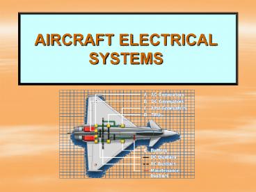
AIRCRAFT ELECTRICAL SYSTEMS
2
Objectives
- Students will be able to
- Describe the basic components of aircraft
electrical system - Explain operation of electrical system
- Interpret aircraft electrical diagram
- Select proper size of wire for installation
- Describe basic causes of electrical system
malfunctions
3
Elements of aircraft electrical systems
- An aircraft electrical system is mainly composed
of - Power sources
- Components
- - Control devices
- - Conversion devices
- - Protection devices.
- Power distribution systems
- Electrical loads
4
Electrical Power Sources
- Electricity power sources on an aircraft may
be classified into two groups - Batteries
- - Lead-acid
- - Nickel-cadmium
- Generators
- - DC generators
- - AC generators
5
Battery
- A battery is a device that converts chemical
energy into electrical energy. - It is a power reservoir that stores energy in
chemical form.It does not produce energy. - Its functions are
- - To provide power when no other power source
is available - - To assist in damping transient loads in the
dc system
6
- - To provide a short term source during
emergency condition - The capacity of battery is measured in
ampere-hours. - Its normal rate is a little over 24vdc in a 28vdc
system. - It is automatically recharged when the
engine-driven generator is operational. - Two types of batteries are used in aircraft
- - Lead-acid batteries
- - Nickel cadmium batteries
7
Lead-acid battery
- It is usually found in piston aircraft.
- It is made up of cells which have
positive/negative plates of lead and filled with
electrolyte of sulfuric acid and water. - Each cell has app. 2.2v, but is simply rated as 2
v. - It has corrosive effects.
- Frequent total discharge and remaining battery in
discharged condition for a long time will shorten
the life of the battery.
8
Battery Cell
9
Nickel cadmium battery
- They are the most common type of battery used in
turboprop and turbojet aircraft. - They provide electrical discharge at a high rate
without voltage drop and accept high charge
rates that shorten recharge time - They may be subject to thermal runaway condition
caused by overheating, in which the battery
destructs itself.
10
Nickel-cadmium battery
Cell Terminals
Vent pipe
Container
Main connector
11
GENERATORS
- A generator is a machine that converts mechanical
energy into electrical energy by the process of
electromagnetic induction - They are driven by the engine(s), and sometimes
by APU. - A generator must be rated at adequate amperage to
drive all the operating components on its
circuit(s). The current required to operate each
electrical component is known as its load.
12
- All generators produce alternating current
naturally.The method which is used to take it
from the coil will determine if the generator
provides ac or dc to the circuit. - If a commutator is used for this purpose it will
be a dc generator. - If a slip ring is used it will be an ac generator.
13
- DC GENERATORS
- Commutator in the generator converts the ac
current to dc current. - DC generator is designed to supply nearly
constant voltage. Usually the voltage is 28vdc,
but there are 270vdc systems developed recently. - They supply current up to 400 A.
- Most aircraft do not have a separate dc
generator, but ac produced by ac generator is
converted to dc to power dc systems.
14
Basic dc generator
15
Operation of a basic dc generator
16
Producing steady dc
17
AC generator (Alternator)
- On most large aircraft high-load electrical
devices are usually AC powered. - AC is produced by ac generator which is usually
called alternator. - AC generators use slip rings instead of
commutators to provide the current to the
circuits. - Alternator generates three-phase current, and
standard aircraft voltage is 115 vac with 400 Hz.
18
Basic ac generator
19
Modern electrical power generation types
- Mainly two types of electrical power
generation currently in use on aircraft. - - Constant frequency Integrated drive
- generators (IDG)
- - Variable speed constant frequency
- (VSCF) generators
20
Constant Speed IDG
- It is essential that the alternator output have a
frequency of 400 Hz with a very small tolerance.
Thus rotational speed of alternator must remain
absolutely constant. - This is accomplished by using a Constant Speed
Drive (CSD) unit between the engine and
alternator. - CSD provides a constant alternator rpm within a
specified engine rpm range.
21
- An alternator and constant speed drive unit
combination is called integrated drive generator
(IDG). - CSD is hydromechanically operated and needs to
be correctly maintained in terms of oil level and
oil cleanliness. - It is the most commonly used power generation
method on today turbine-powered aircraft.
22
Integrated Drive Generator
23
Constant speed drive
24
Constant Speed Drive
25
VSCF
- In this method, the variable frequency power
produced by the alternator is converted to
constant frequency 400 Hz, 115 vac by solid-state
devices electronically. - Thus there is no need for CSD unit.
- It is a new technique and limited in use.
26
Variable speed constant frequency generator
27
Power Generation Control
- Power produced by generators is usually
controlled by generator control unit (GCU). - The main functions of this device are
- - Act as a voltage regulator
- - Direct current to battery for recharging
- - Provide circuit and generator protection
- by disconnecting the generator from the
- system when electrical abnormalities
- occur.
28
Control Devices
- These devices are use to initiate and control the
operation of the circuits.Control devices include - Switches
- Rheostats
- Relays
- Solenoids
29
Switches
- A switch is used to start, to stop, or to change
the direction of the current flow in the circuit. - Toggle switches They are on/off switches and
extensively used in aircraft electrical system. - Push Switches They are used primarily for
operations of short durations - Rotary switches When it is necessary to select
several condition for a circuit, a rotary switch
may be used.
30
Rotary Switch
31
Toggle switch
32
- Rheostats control the amount of current that
flows throughout the circuit and used as dimmer
devices for instrument and cockpit lights. - Relays Electromagnetic switching devices which
are used to remotely control electric circuits
carrying large amount of current. - Solenoids Remote control devices quite similar
to relays but they are designed to move a shaft
over a short distance. Thus, solenoids are used
as mechanical control devices to operate
hydraulic or pneumatic valves, locking pins, etc.
33
Rheostat
34
Schematic of a relay
35
Relay
36
Conversion Devices
- There are many occasions within an aircraft
electrical system where it is required to convert
power from one form to another. - Typical examples of power conversion are
- - Conversion from dc to ac power
- - Conversion from 115vac to 28 vdc
- - Conversion from one ac voltage level to another
- - Battery charging (from 115vac to 28vdc)
37
- Following devices are used for these purposes
- Transformers
- Rectifiers
- Transformer-rectifier units (TRUs)
- Inverters
- Transistors
38
- Transformers Used to change ac voltage level.
- Rectifiers Used to convert ac into
high-amperage, low-voltage dc. - TRUs Combination of transformers and rectifiers
and used as main unit to convert alternator
output to dc in an aircraft - Inverters convert 28 vdc power to 26 vac power
particularly for flight instruments or 115 vac. - Transistors Electronic devices that control
electron flow and convert ac to dc.
39
Transformer
40
Analogy to TRU (ac adapter)
41
TRUs
42
Inverter
43
Analogy to inverter (ups for computer)
44
Protection Devices
- These devices are used to protect circuits,
cables and system components from damage due to
failures. - Fuses
- Circuit breakers
- Diodes
- GCUs
45
- Fuses They are designed to protect the cables
against the flow of short-circuit and excessive
current. They break the circuit and stop the
current flow when the current exceeds a
predetermined value. - Circuit breakers They have same function with
the fuses.The difference from the fuse is that
they are resettable, while a fuse must be
replaced. - Diodes They are the electronic equivalent to
the check valves in hydraulic system. They allow
electricity to flow in one way only.
46
Circuit Breakers
47
Circuit Breakers
48
Primary Causes of Electrical Circuit Failures
- Open circuit
- It is a circuit that is not complete or
continuous. This is an uncommanded interruption
of electrical power tosome components or systems.
When an open occurs the affected component stop
to operate, but the other components still remain
in operative condition.
49
Common causes of open circuit
50
- Short Circuit
- It occurs when electricity is allowed to take
a shortcut through or around a component or
system. This is the most serious problem. It has
two effects - - Affected components have no power
- and fail to operate
- - Since current will not flow through
- affected components, the other
- components will be subjected to higher
- level of current causing them to burn
- out.
51
Common causes of a short
52
Power Distribution
- An electrical distribution system is required
in order to convey the electrical power to the
equipments and systems that need it. - Busbar systems
- Wire and cables
53
Busbar System
- In most types of aircraft, output from the
generators is sent to one or more conductors
before distribution throughout the system. - These conductors are called busbars and they act
as distribution centers for electric power. - A busbar system is set up so that each power
source supplies one or more specific buses.
54
Analogy to bus
55
- A variety of electrical items are hooked up to
each bus for power. - The buses are interconnected via circuit
protection devices which are called bus ties. - Bus ties are switches or relays used to connect
or disconnect buses from one another. - They serve to isolate failed buses from working
ones and/or send electrical power to buses that
lost their normal power sources.
56
- Each engine-driven generator, for example,
normally drives its own generator bus.
High-current drawn items are connected to these
buses. - Items like fixed fire extinguishers and emergency
lights are usually powered off battery bus. That
way they are powered for use even when no
generator power is available.
57
Typical 28vdc system
58
WIRES AND CABLES
- Wires and cables conduct electrical power in its
various forms and quantities to and between
equipments. - There are various types of wires used in aircraft
electrical system. The conductor is made of
copper or aluminum. The insulation material may
be nylon, PVC, or fiberglass.
59
Aircraft wires
60
Wire size selection
- The wires installed in an aircraft electrical
system are chosen on the basis of ability to
carry the required current - - without overheating and
- - without producing an excessive voltage
- drop.
- Electrical wire charts may be used for this
purposes.
61
Maximum voltage drop in load circuits
62
Wire chart
63
Electrical wire size measurement
64
Aircraft wiring diagrams
- There are different types of electrical diagrams
available to understand electrical systems. These
diagrams may be in the following forms - - Block diagrams
- - Pictorial diagrams
- - Schematic diagrams
- Many symbols are used in these diagrams.
65
Pictorial electric diagram
66
ELECTRICAL DIAGRAM
67
Aircraft electrical system diagram
68
Electrical loads
- Once the aircraft electrical power has been
generated and distributed then it is available to
the aircraft services. - These electrical services are distributed
throughout the aircraft and may be broadly
subdivided into following categories. - Motors
- Lighting services
- Heating services
- Avionics
69
Aircraft Lighting System
- Lighting system represent an important element
of the aircraft electrical services. - External lighting systems
- Internal lighting systems
70
External lighting system
- Provides illumination for such operation as
landing at night, inspection of icing condition,
and safety from midair collision. - Most common aircraft exterior lights
- Position lights (navigation lights)
- Landing/taxi lights
- Anti-collision lights
- Inspection lights
71
- Position lights
- - Red at left wing tip
- - Green at right wing tip
- - White at vertical stabilizer
- Anti-collision lights
- - Rotating beam lights
- - Usually at the top of fuselage or tail
- Landing and taxi lights
- - Landing lights at the leading edge of wings
- - Taxi lights at nose landing gear
72
Exterior lights
73
Aircraft exterior lights
74
Exterior lights
75
Exterior lights
76
Exterior lights
77
Exterior lights