
L2 FUEL SYSTEMS L2 FUEL SYSTEMS Revision from yr 1 Types of - PowerPoint PPT Presentation
1 / 66
Title:
L2 FUEL SYSTEMS L2 FUEL SYSTEMS Revision from yr 1 Types of
Description:
L2 FUEL SYSTEMS L2 FUEL SYSTEMS Revision from yr 1 Types of Fuel Systems SI Fuel Systems CI Fuel Systems Hybrid Fuel Systems L2 FUEL SYSTEMS Revision from yr 1 Fuel ... – PowerPoint PPT presentation
Number of Views:618
Avg rating:3.0/5.0
Title: L2 FUEL SYSTEMS L2 FUEL SYSTEMS Revision from yr 1 Types of
1
L2 FUEL SYSTEMS
2
L2 FUEL SYSTEMS
- Revision from yr 1
- Types of Fuel Systems
- SI Fuel Systems
- CI Fuel Systems
- Hybrid Fuel Systems
3
L2 FUEL SYSTEMS
- Revision from yr 1
- Fuel utilised in SI Systems
- Petrol
- LPG
- Natural Gas ( Liquid or Compressed)
- Hydrogen Cells
4
L2 FUEL SYSTEMS
- Revision from yr 1
- Fuel utilised in CI Systems
- Diesel
- Bio Diesel
- Red Diesel (Legality)
- Any oil based fuels (Legality User)
5
L2 FUEL SYSTEMS
- Revision from yr 1
- Fuel utilised in Hybrid Systems
- Any fuel used in SI or CI systems
- Plus the transfer to battery power for given
engine operating conditions
6
L2 FUEL SYSTEMS
- Purpose
- To Introduce fuel/air into the engine
- To ensure correct ratio of fuel/air for given
engine operating conditions - To ensure adequate vaporization and mixing of
fuel/air occurs
7
L2 FUEL SYSTEMS
- SI Fuel Systems
- Methods of introducing fuel to air
- Carburettors
- Fuel Injection
8
L2 FUEL SYSTEMS
- Air Fuel Ratio
- To ensure complete fuel combustion the correct
air/fuel ratio must be achieved - Air/fuel ratio is the weight of air relative to
weight of fuel - For SI engines the chemically correct ratio is
- 14.7 1 ie 14.7 g air 1 g fuel
- The correct term for this is the stoichmetric
mixture
9
L2 FUEL SYSTEMS
- Exhaust Emission
- The main exhaust gases are
- Carbon Monoxide CO
- Hydrocarbons HC
- Carbon Dioxide CO2
- Oxygen
- Oxides of Nitrogen NOx
10
L2 FUEL SYSTEMS
- Products of Combustion
- Weak Mixture
- Produces
- Oxygen (O)
- Carbon Dioxide (CO2)
- NOX
- If too weak and increase in Hydrocarbons (HC)
11
L2 FUEL SYSTEMS
- Products of Combustion
- Correct Mixture
- Produces
- Carbon Dioxide (CO2)
- Water (H20)
12
L2 FUEL SYSTEMS
- Products of Combustion
- Rich Mixture
- Produces
- Carbon Dioxide (CO2)
- Carbon Monoxide (CO)
- Water (H20)
- And possibly Carbon (C) and Hydro Carbons (HC) ie
black smoke
13
L2 FUEL SYSTEMS
- Health and Safety
- Storage of Fuel in the workshop
- Covered by the Petroleum Spirit Regulations
- ie Licensed to hold a specific amount
- Stored in secure and approved building external
to main building
14
L2 FUEL SYSTEMS
- Health and Safety
- Sitting and construction of SI fuel tanks
- Must not be venerable to impact during an
accident - Must be so designed as not to split under impact
conditions - (See Construction and Use Regulations)
15
L2 FUEL SYSTEMS
- SI FUEL CARBURATION SYSTEMS
16
L2 FUEL SYSTEMSMain Components
Manufactured from steel but increasingly common
on modern vehicle plastic WHY PLASTIC?? The tank
will include An air vent to allow air to
replace the petrol taken from the tank. A fuel
level indicator to show how much petrol is left
in the tank. Baffles to stop the petrol moving
around inside the tank. This makes the vehicle
safer when cornering. A means of preventing fuel
or vapours escaping during use or the event of an
accident
17
FUEL PUMPS
The mechanical fuel pump is fitted to the engine
and driven by the camshaft. The electrical fuel
pump is normally mounted near the fuel tank. The
fuel pump draws fuel from the tank and pumps it
to the carburettor.
18
MECHANICAL FUEL PUMP
FUEL OUT
FUEL IN
INLET VALVE
DELIVERY VALVE
DIAPHRAGM
DIAPHRAGM SPRING
PULL ROD SEAL
ECCENTRIC ON CAMSHAFT
Drain Hole Acts as a breather for diaphragm, but
is also a tell-tale hole - fuel will leak out of
it if the diaphragm splits. Oil will leak out if
the piston rod seal fails.
19
OPERATION
- The two levers AB are operated by the eccentric.
The eccentric pushes the lever B up which then
forces lever A and the diaphragm down by means of
contact between the two drive faces. The
diaphragm - WILL REMAIN DOWN UNTIL THE ENGINE HAS USED SOME
PETROL SO THE LARGE SPRING CAN PUSH THE DIAPHRAGM
UP. - The small spring by the drive faces keeps the
lever in contact with the eccentric giving
quieter operation. Some pumps have a small,
restricted, return pipe connecting the pump
outlet chamber to the tank. This allows a small
amount of fuel to return to the tank so
preventing excess pressure build up which would
otherwise force excess petrol into the carburetor.
20
PLUNGER TYPE MECHANICAL PUMP
- Modern practice is to use a plunger type pump
which operates on a similar principal but uses a
plunger instead of a lever arm. - This type of pump is illustrated on the next
slide, the lower portion has been lengthened to
show the "lost motion" feature.
21
PLUNGER TYPE MECHANICAL PUMP
Lost Motion
22
MECHANICAL FUEL PUMPTESTING
- Testing requires a pressure gauge and a vacuum
gauge. - Attach the vacuum gauge to the inlet and operate
the pump until maximum vacuum is obtained. Stop
pumping and watch the gauge - The vacuum should be about 150 mm Hg and the
vacuum should not drop more than 50mm Hg in 15
seconds. Remove the vacuum gauge.
23
MECHANICAL FUEL PUMP
- Attach the pressure gauge to the outlet and
operate the pump until maximum pressure is
obtained - The pressure should be at least 0.2
bar/21 kPa/3 psi and the pressure should not drop
more than 0.5 bar in 15 seconds. Remove pressure
gauge - If testing a pump which has been in store for a
period of time the valves will need wetting -
either pump white spirit/paraffin through it or
spray the inlet an outlet with WD40 whilst
operating the pump.
24
FAULT DIAGNOSIS
25
FUEL PUMP VIDEOS
MECHANICAL FUEL PUMP
26
Electric Fuel Pumps - Low Pressure
9
8
7
1
2
4
5
3
6
12
1 Contact Breaker Points 2 Magnet Coil 3 Return
Spring 4 Outlet Valve 5 Outlet Connection 6
Electrical Supply Connection 7 Pushrod
8 Magnet Armature 9 Diaphragm Assembly 10 Inlet
Valve 11 Inlet Connection 12 Filter
11
10
27
Electric Fuel PumpsLow Pressure
- Operation
- Only suitable for carburettors
- Utilises a diaphragm in the same way as a
mechanical pump - Push rod movement controlled by a electro
magnetic solenoid action - If push rod movement restricted contacts remain
open and pump closes down until full movement
available
28
Electric Fuel PumpsHigh Pressure
- For fuel injection systems a high pressure pump
is required, for this a roller cell pump is used
29
Electric Fuel PumpsHigh Pressure
- Operation
- Uses a roller cell pump driven by a permanent
magnet motor - Rotation of the pump moves the rollers outwards
and seals the space between rotor and casing - Fuel is carried around the rotor and decrease in
volume increases the pressure - Fuel passing through the motor aids in cooling
30
Electric Fuel PumpsHigh Pressure
- The pump produces excess fuel which is
recalculated back to the tank reducing the risk
of vapour lock - Two ball valves are fitted to the pump, a
pressure relief valve and a non return valve at
the pump outlet - Pump operation is ECM controlled
- As the pump as high pressure but low suction
normally installed inside the fuel tank
31
FUEL PUMP VIDEOS
ELECTRICAL FUEL PUMP
32
FUEL FILTERS
Fuel filters are used to filter particles and
dirt from the fuel to protect the system.
Made from either plastic or metal, with a paper
element and are fitted in-line or mounted in a
housing. Note some fuel filters have a
Non-Return Valve (N.R.V.), which only allows flow
in one direction look for an arrow on the
filter, which indicates the direction of flow.
33
FUEL FILTERS
- Purpose of Fuel Filters
- To filter impurities such as fine dirt particles
and water - These enter the fuel tank whilst refilling
- Filters are usually directional oriented
- They must be changed periodically
34
FUEL FILTERS
35
FUEL FILTERS
36
Types of SI Fuel Systems
- Carburettors (No longer used for modern vehicles
due to emission laws) - Throttle Body (single point) Injection
- Multi Point Injection
- Continuous
- Sequential
- Direct SI Fuel Injection (GDI)
37
Types of Carburettors
- Note This is for information only
- Fixed Choke
- Variable Choke
- Twin Choke
- Twin Barrel
38
THE FIXED CHOKE CARBURETTOR
39
THE VARIABLE CHOKE CARBURETTOR
40
Principals of a CarburettorSimple Fixed Choke
41
Principals of a CarburettorSimple Fixed Choke
- Works on the simple U-tube principle
- Whilst the pressure in the float chamber and the
choke are equal fuel level is also equal - Should pressure drop in the choke fuel will rise
in the tube and spill into the intake - Due to the venturi air drawn into the engine will
speed up causing a depression around the tube - The increase in air speed also ensures fuel spilt
out is readily mixes with the air - Issue! Only effective over a limited speed range
- No Variation in mixture settings possible
42
Principals of a CarburettorComplex Fixed Choke
43
Principals of a CarburettorComplex Fixed Choke
- Additional jets are fitted to allow mixture
control over a wide range of engine operating
conditions - A Slow running jet allows the mixture to be
controlled at tick over - Compensation jets and progression jets allow the
mixture to be formulated from tick over to
cruising and full throttle - An accelerator jet gives a excessive rich mixture
to cope with sudden bursts of speed - Cold start conditions are controlled by the
fitment of a strangler flap to restrict air flow
and provide a rich mixture
44
Video
45
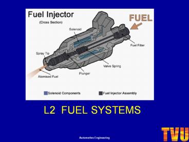
INJECTORS (SI)
- The purpose of the injector is to inject the
correct amount of fuel at the correct time. - Injectors can be
- Single point
46
INJECTORS (SI)
- Multi-point
47
ELECTRONIC FUEL INJECTION SYSTEMS
CDX Video Electronic Fuel Injection systems
48
FUEL INJECTION COMPONENTS
Fuel injection systems also require many other
components to function correctly, these include
- Throttle Potentiometer
- A device normally mounted on the throttle body
- which tells the ECU the position of the throttle
pedal.
2. Idle Speed Control Valve A device normally
mounted on the throttle body which controls the
idle speed by adjusting the amount of air
entering the manifold. Receives instructions
from the ECU.
49
FUEL INJECTION COMPONENTS
3. Auxiliary Air Device Designed to assist the
engine when starting from cold by opening a small
port to increase the idle speed.
- Lambda Sensor
- Also known as an exhaust gas oxygen sensor
(EGO/O2). - Readings from this sensor are used by the ECU to
balance the fuel mixture.
50
FUEL INJECTION COMPONENTS
- Mass Air Flow (MAF) Sensors
- This sensor converts the amount of air drawn
into the engine into a voltage signal. The ECU
uses this to calculate engine load.
6. Manifold Absolute Pressure (MAP) Sensor A
variable resistor used to monitor the difference
in pressure between the Inlet manifold and
outside atmospheric pressure.
51
FUEL INJECTION COMPONENTS
7. Engine Control Unit (ECU) (also known as
Engine Control Module (ECM) Powertrain Control
Module/Unit (PCM/PCU). ECUs determine the
quantity of fuel, ignition timing, variable valve
timing, turbocharger and other parameters by
monitoring the engine through sensors. These
can include MAP sensor Throttle position
sensor Air temperature sensor Oxygen
sensor Lambda sensor Mass airflow sensor and
many others.
52
FUEL INJECTION COMPONENTS
- Fuel Pressure Regulator
- Maintains the fuel pressure in the
- system at the correct pressure.
- Connected to the MAP sensor allows fuel pressure
to be relative to manifold pressure
9. Relays Are an electrical switch that are
controlled by a separate circuit to the one they
are operating. i.e. Headlights, Starter motor,
Fuel pump etc.
53
FUEL INJECTION COMPONENTS
10. Exhaust Gas Recirculation Valve A valve that
recirculates some (5 15) of the exhaust gases
back to the inlet manifold. This reduces NOx
(Nitrogen Oxide/Dioxide).
54
FUEL INJECTION ANCILLARIES
1. Bleed Points If the vehicle runs out of
fuel, or fuel system components are replaced,
some vehicles require the air to be removed from
the fuel system before the vehicle will start
(especially true on diesels). Bleed points are
provided on fuel systems to remove air from the
system. Most modern systems are however self
bleeding
2. Cold Start Aids When the engine is cold, it
requires a rich fuel mixture to help it start.
Petrol systems have various methods available.
Carburettors have a choke device which reduces
the amount of air entering the combustion
chamber, injection systems normally inject extra
fuel into the combustion chamber. Diesel cold
start systems are covered later.
55
Single Point/Throttle Body Injection
56
Single Point/Throttle Body Injection
- Schematic View
57
Single Point/Throttle Body Injection
- Advantages
- More efficient than carburettors
- Better fuel atomisation
- More precise control of air/fuel ratios
- Uses less fuel on cold start and warm up
- Disadvantages
- Not as efficient as multipoint injection
- Poor fuel distribution
- Higher emissions than multipoint
- Prone to flat spots at low engine speeds
58
Single Point/Throttle Body Injection
- Operation
- Utilises a single solenoid-operated injector
situated centrally in the air intake above the
throttle butterfly - Fuel supply is a pressurized system via a roller
cell fuel pump normally around 1 Bar. Fuel
pressure is controlled by the fuel pressure
regulator which returns excess fuel back to the
fuel tank - Injected fuel is directed into the venturi shaped
region around the throttle butterfly, thus the
increased air speed further atomises the fuel - Injection is continuous
- Volume of air is normally monitored by the MAP
(manifold absolute pressure) sensor - Most system also monitor throttle position and
rate of throttle movement - The system also incorporates the range of
additional sensors previously mentioned
59
Multi Point Injection
- Schematic View
60
Multi Point Injection
- Operation
- Utilised either continuous or sequential
injection modes - High pressure fuel is supplied to the fuel rail
via a roller cell pump (normally around 3 bar) - The injectors which are ECU controlled are
solenoid operated - The ECU controls the period or duration the
injector stays open dependent on engine fuel
requirements - Injection is aimed at the back of the valve head
- Amount of fuel is determined by the mass of air,
throttle position, engine speed, MAP, density of
air and temperature of the engine as the main
parameters
61
Multi Point Injection
- Advantages
- Excellent fuel distribution
- Extremely fine control on amount of fuel injected
- Good emissions
- Reduced fuel consumption
- Smoother engine operation due to even power
output per cylinder - Automatic adjustment of fuelling to suit all
engine operating conditions
62
CI Fuel Systems
63
CI Fuel Systems
64
(No Transcript)
65
(No Transcript)
66
Common Rail
- Common rail direct fuel injection is a modern
variant of direct fuel injection system for
petrol and diesel engines. - On diesel engines, it features a high-pressure
(over1,000 bar/15,000 psi) fuel rail feeding
individual solenoid valves, as opposed to
low-pressure fuel pump feeding unit injectors
(Pumpe Düse or pump nozzles), or high-pressure
fuel line to mechanical valves controlled by cams
on the camshaft. Third-generation common rail
diesels now feature piezoelectric injectors for
increased precision, with fuel pressures up to
1,800 bars (26,000 psi).
Recommended
CrystalGraphics Presentations


