
Energy Conservation (Bernoulli - PowerPoint PPT Presentation
Title:
Energy Conservation (Bernoulli
Description:
Energy Conservation (Bernoulli s Equation) Recall Euler s equation: Also recall that viscous forces were neglected, i.e. flow is invisicd If one integrates Euler ... – PowerPoint PPT presentation
Number of Views:356
Avg rating:3.0/5.0
Title: Energy Conservation (Bernoulli
1
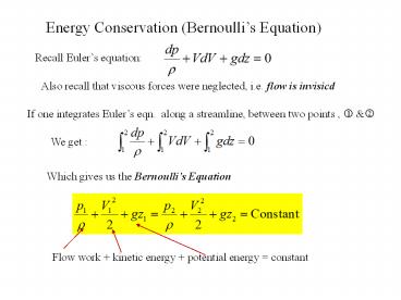
Energy Conservation (Bernoullis Equation)
Recall Eulers equation
Also recall that viscous forces were neglected,
i.e. flow is invisicd
If one integrates Eulers eqn. along a
streamline, between two points , ? ?
We get
Which gives us the Bernoullis Equation
Flow work kinetic energy potential energy
constant
2
Bernoullis Equation (Continued)
Flow Work (p/?) It is the work required to
move fluid across the control volume boundaries.
Consider a fluid element of cross-sectional area
A with pressure p acting on the control surface
as shown.
Due to the fluid pressure, the fluid element
moves a distance Dx within time Dt. Hence, the
work done per unit time DW/Dt (flow power) is
Flow work or Power
Flow work per unit mass
1/mass flow rate
Flow work is often also referred to as flow energy
3
Bernoullis Equation (Cont)
Very Important Bernoullis equation is only
valid for incompressible fluids, steady flow
along a streamline, no energy loss due to
friction, no heat transfer.
Application of Bernoullis equation - Example 1
Determine the velocity and mass flow rate of
efflux from the circular hole (0.1 m dia.) at the
bottom of the water tank (at this instant). The
tank is open to the atmosphere and H4 m
p1 p2, V10
1
H
2
4
Bernoullis Eqn/Energy Conservation (cont.)
Example 2 If the tank has a cross-sectional area
of 1 m2, estimate the time required to drain the
tank to level 2.
1
First, choose the control volume as enclosed by
the dotted line. Specify hh(t) as the
water level as a function of time.
h(t)
2
5
Energy exchange (conservation) in a thermal system
Energy added, hA (ex. pump, compressor)
Energy lost, hL (ex. friction, valve, expansion)
Energy extracted, hE (ex. turbine, windmill)
hL loss through valves
heat exchanger
hE
hA
pump
turbine
hL, friction loss through pipes
hL loss through elbows
condenser
6
Energy conservation(cont.)
If energy is added, removed or lost via pumps
turbines, friction, etc.then we use
Extended Bernoullis Equation
Example Determine the efficiency of the pump if
the power input of the motor is measured to be
1.5 hp. It is known that the pump delivers 300
gal/min of water.
No turbine work and frictional losses, hence
hEhL0. Also z1z2
Given Q300 gal/min0.667 ft3/sAV ?V1
Q/A13.33 ft/s V2Q/A27.54 ft/s
4-in dia.pipe
6-in dia. pipe
Looking at the pressure term
Mercury (?m844.9 lb/ft3) water (?w62.4
lb/ft3) 1 hp550 lb-ft/s
7
Energy conservation (cont.)
Example (cont.)
8
Frictional losses in piping system
P1
R radius, D diameter L pipe length ?w wall
shear stress
P2
Consider a laminar, fully developed circular pipe
flow
?w
Pdp
p
Darcys Equation
9
(No Transcript)
10
(No Transcript)
11
Losses in Pipe Flows
Major Losses due to friction, significant head
loss is associated with the straight portions of
pipe flows. This loss can be calculated using
the Moody chart or Colebrook equation. Minor
Losses Additional components (valves, bends,
tees, contractions, etc) in pipe flows also
contribute to the total head loss of the system.
Their contributions are generally termed minor
losses. The head losses and pressure drops can
be characterized by using the loss
coefficient, KL, which is defined as One of the
example of minor losses is the entrance flow
loss. A typical flow pattern for flow entering
a sharp-edged entrance is shown in the following
page. A vena contracta region is formed at the
inlet because the fluid can not turn a sharp
corner. Flow separation and associated viscous
effects will tend to decrease the flow
energy the phenomenon is fairly complicated. To
simplify the analysis, a head loss and the
associated loss coefficient are used in the
extended Bernoullis equation to take
into consideration this effect as described in
the next page.
12
Minor Loss through flow entrance
V1
V2
V3
(1/2)?V32
(1/2)?V22
KL(1/2)?V32
p?p?
13
Energy Conservation (cont.)
Let us now also account for energy transfer via
Heat Transfer, e.g. in a heat exchanger The most
general form of conservation of energy for a
system can be written as dE dQ-dW
where (Ch. 3, YAC)
- dE ? Change in Total Energy, E
- and E U(internal energy)Em(mechanical energy)
(Ch. 1 YAC) - E U KE (kinetic energy) PE(potential
energy) - dW ? Work done by the system where
- W Wext(external work) Wflow(flow work)
- dQ Heat transfer into the system (via
conduction, convection radiation) - Convention dQ gt 0 net heat transfer into the
system (Symbols Q,q..) - dW gt 0, positive work done by the system
- Q What is Internal Energy ?
mechanical energy
14
Energy Conservation (cont.)
U mu, u(internal energy per unit mass), KE
(1/2)mV2 and PE mgz Flow work Wflow m
(p/?) It is common practice to combine the total
energy with flow work. Thus
The difference between energy in and out is due
to heat transfer (into or out) and work done (by
or on) the system.
15
Energy Conservation (cont.)
- Hence, a system exchanges energy with the
environment due to - Flow in/out 2) Heat Transfer, Q and 3) Work, W
- This energy exchange is governed by the First Law
of Thermodynamics
Heat in, dQ/dt
system
Work out dW/dt
Enthalpy
16
Conservation of Energy Application
Example Superheated water vapor enters a steam
turbine at a mass flow rate 1 kg/s and exhausting
as saturated steam as shown. Heat loss from the
turbine is 10 kW under the following operating
condition. Determine the turbine power output.
From superheated vapor tables hin3149.5 kJ/kg
P1.4 Mpa T350? C V80 m/s z10 m
10 kw
P0.5 Mpa 100 saturated steam V50 m/s z5 m
From saturated steam tables hout2748.7 kJ/kg
17
Q, q ?!
Back
- Internal Energy ?
- Internal energy, U (total) or u (per unit mass)
is the sum of all - microscopic forms of energy.
- It can be viewed as the sum of the kinetic and
potential energies of the molecules - Due to the vibrational, translational and
rotational energies of the moelcules. - Proportional to the temperature of the gas.
Back
Recommended
CrystalGraphics Presentations


