
Reciprocating Engine Design and Construction - PowerPoint PPT Presentation
1 / 66
Title:
Reciprocating Engine Design and Construction
Description:
Reciprocating Engine Design and Construction Reciprocating Engine Design and Construction Basic Parts Crankcase Cylinders Pistons Connecting rods Valves Valve ... – PowerPoint PPT presentation
Number of Views:3945
Avg rating:5.0/5.0
Title: Reciprocating Engine Design and Construction
1
Reciprocating Engine Design and Construction
2
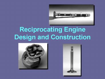
Reciprocating Engine Design and Construction
- Basic Parts
- Crankcase
- Cylinders
- Pistons
- Connecting rods
- Valves
- Valve-operating mechanism
- Crankshaft
- Head
- Spark plugs
3
Reciprocating Engine Design and Construction
- Crankcase
- Foundation of the engine, containing the bearings
in which the crankshaft revolves.
4
Reciprocating Engine Design and Construction
- Crankcase
- Tight enclosure for lubricating oil.
- Support for attachment of the cylinders and the
powerplant to the aircraft. - Must be rigid, strong and light.
- Cast of forged aluminum alloy.
5
Reciprocating Engine Design and Construction
- Opposed Engine Crankcase
Bearings
6
Reciprocating Engine Design and Construction
- Crankshafts
- Transforms the reciprocating motion of the piston
and connecting rod into rotary motion for the
propeller.
7
Reciprocating Engine Design and Construction
- Crankshaft
- Backbone of engine.
- Forged from very strong alloy (Chromium-nickel-mol
ybdenum steel). - Single or multi-piece.
8
Reciprocating Engine Design and Construction
- Crankshaft
- Four-throw used on four-cylinder engines.
- Six-throw used on six-cylinder engines.
- Three Main Parts
- Journal
- Crankpin
- Crankcheek
9
Reciprocating Engine Design and Construction
- Crankshaft Balance
- Dynamic dampers are used to reduce vibration
during engine operation. - Pendulum which
- is fastened to the
- crankshaft.
10
Reciprocating Engine Design and Construction
- Connecting Rods
- Link which transmits forces between the piston
and the crankshaft.
Master and Articulated
Fork and Blade
Plain
11
Reciprocating Engine Design and Construction
- Master and Articulated Rod Assembly
- Commonly used in radial engines.
- One piston in each row is connected to the master
rod. Others are connected to the master rod by
articulated rods.
12
Reciprocating Engine Design and Construction
- Fork And Blade Assembly
- Used primarily in V-type engines.
13
Reciprocating Engine Design and Construction
- Plain Type Connecting Rod
- Used in in-line and opposed engines.
14
Reciprocating Engine Design and Construction
- Pistons
- Acts as a moving wall within the combustion
chamber.
15
Reciprocating Engine Design and Construction
- As the piston moves down it draws in fuel/air
mixture. - As it moves up it compresses the charge.
- Ignition occurs, and expanding gases force the
piston down. - This force is transmitted to crankshaft through
connecting rod. - On the return upward stroke, the piston forces
the exhaust gas out.
16
Reciprocating Engine Design and Construction
- Piston Construction
- Machined from aluminum alloy forgings.
- Grooves machined for piston rings.
- Cooling fins inside for
- greater heat transfer.
- Piston pin (wrist pin)
- joins the piston to the
- connecting rod.
17
Reciprocating Engine Design and Construction
- Piston Types
- Trunk Type
- Slipper Type
- Not used in aircraft
Slipper
Trunk
18
Reciprocating Engine Design and Construction
- Piston Rings
- Compression Rings
- Oil Control Rings
- Oil Scraper Rings
Rings
Pin boss
19
Reciprocating Engine Design and Construction
- Compression Rings
- Prevent the escape of gas past the piston during
engine operation. - Number used depends on engine design.
- Cross section of the ring is either rectangular
or wedge shaped
20
Reciprocating Engine Design and Construction
- Oil Control Rings
- Placed in grooves immediately below the
compression rings. - One or more rings per piston.
- Regulate the thickness of the oil film on the
cylinder wall.
21
Reciprocating Engine Design and Construction
- Oil Scraper Ring
- Installed in the groove at the bottom of the
piston skirt. - Installed with the scraping edge away from the
piston head or in the reverse position. - Returns surplus oil to the
- crankcase.
22
Reciprocating Engine Design and Construction
- Cylinders
- The portion of the engine in which the power is
developed. - Provides a combustion chamber where the burning
and expansion of gases take place. - Houses the piston and
- the connecting rod.
23
Reciprocating Engine Design and Construction
- Cylinders
- Either produced singly or cast in a block.
- Air-cooled engine uses
- the overhead valve type.
- Two major parts Head,
- Barrel.
24
Reciprocating Engine Design and Construction
- Cylinder Heads
- Provides a place for combustion of the fuel/air
mixture. - Gives the cylinder more heat conductivity for
cooling. - Contains the intake valve, exhaust valve and
sparkplugs. - Contains fins for cooling.
25
Reciprocating Engine Design and Construction
- Cylinder Barrels
- Made of a steel alloy forging with the inner
surface hardened to resist wear. (Nitrided) - Worn Cylinder walls can be ground out and
re-nitrided or chrome plated. - Chrome plated cylinders can be recognized by
orange paint mark on cylinder.
26
Reciprocating Engine Design and Construction
- Cylinder Numbering (Opposed Engine)
- Propeller
- (Front)
- Accessory
- (Rear)
- Left, right
- (Pilots view)
27
Reciprocating Engine Design and Construction
- Cylinder Numbering (Opposed Engine)
- Numbering is by no means standard.
- Continental starts from rear.
- Lycoming starts from front.
28
Reciprocating Engine Design and Construction
- Cylinder Numbering (Radial Engine)
29
Reciprocating Engine Design and Construction
- Cylinder Numbering (Radial Engine)
- Numbered clockwise as viewed from the accessory
end. - Single-row, cylinder No. 1 is the top cylinder.
- Double-row, all odd-numbered cylinders are in the
rear, and all even numbered cylinders are in the
front.
30
Reciprocating Engine Design and Construction
- Firing Order
- The Sequence in which the power event occurs in
the different cylinders. - Designed to provide for balance and to eliminate
vibration.
31
Reciprocating Engine Design and Construction
- Firing Order Single-Row-Radial
- First all odd numbered cylinders fire in
numerical succession. - Then the even-numbered cylinders fire in
numerical succession. - 1-3-5-7-9-2-4-6-8
32
Reciprocating Engine Design and Construction
- Firing Order Double-Row-Radial
- Arranged with the firing impulse occurring in a
cylinder in one row and then in a cylinder in the
other row. - Two cylinders in the same row never fire in
succession.
33
Reciprocating Engine Design and Construction
- Firing Order Opposed Engine
- Lycoming and Continental number their cylinders
differently which gives us two sets of firing
orders. - But the firing impulses are the same.
34
Reciprocating Engine Design and Construction
- Firing Order Opposed Engine
1-4-2-3
35
Reciprocating Engine Design and Construction
- Valves
36
Reciprocating Engine Design and Construction
- Valves
- Fuel/air mixture enters the cylinders through the
intake valve. - Burned gases are expelled through the exhaust
valve. - Mushroom or tulip type depending on shape.
37
Reciprocating Engine Design and Construction
38
Reciprocating Engine Design and Construction
- Valve Construction
- Intake valves, because of lower operating
temperatures, can be made of chrome-nickel steel. - Exhaust valves are made of exotic metals such as
inconel, silicon-chromium or cobalt-chromium
alloys.
39
Reciprocating Engine Design and Construction
- Valve Construction
Stem
40
Reciprocating Engine Design and Construction
- Valve Construction
- Valve head has ground face which forms a seal
against the ground valve seat in the cylinder
head. - Valve face ground to an angle of either 30 or
45. - Valve face made more durable by the application
of stellite (an alloy of cobalt and chromium).
41
Reciprocating Engine Design and Construction
- Valve Construction
- Valve stem acts as a pilot for the valve head and
rides in the valve guide. - Surface-hardened to resist wear.
- Some stems are hollow and partially filled with
metallic sodium.
42
Reciprocating Engine Design and Construction
- Valve Construction
- The neck is the part that forms the junction
between the head and the stem. - The tip is hardened to with stand the hammering
of the valve rocker arm.
43
Reciprocating Engine Design and Construction
- Valve Construction
- Machined groove near tip receives the split-ring
keys which form a lock ring to hold the valve
spring retaining washer.
44
Reciprocating Engine Design and Construction
- Valve-Operating Mechanism
- Each valve must open at the proper time, stay
open for the required length of time, and close
at the proper time. - Timing of the valves is controlled by the
valve-operating mechanism.
45
Reciprocating Engine Design and Construction
- Valve-Operating Mechanism
- Intake valves open just before the piston reaches
top dead center, and exhaust valves remain open
after top dead center. - At this particular instant both valves are open
at the same time (end of the exhaust stroke and
beginning of the intake stroke). - This valve overlap results in better volumetric
efficiency and lower operating temperatures.
46
Reciprocating Engine Design and Construction
- Valve-Operating Mechanism (Opposed engine)
47
Reciprocating Engine Design and Construction
- Valve-Operating Mechanism
- (Radial engine)
48
Reciprocating Engine Design and Construction
- Camshaft
- Valve-operating mechanism is operated by a
camshaft.
49
Reciprocating Engine Design and Construction
- Camshaft
- The camshaft is
- driven by a gear
- that mates with
- another gear
- attached to the
- crankshaft.
50
Reciprocating Engine Design and Construction
- Tappet Assembly
- Converts rotational movement of the cam lobe into
reciprocating motion. - Transmits this motion to the push rod, rocker
arm, and then to the valve tip. - Opening the valve at the proper time.
51
Reciprocating Engine Design and Construction
- Tappet Assembly
52
Reciprocating Engine Design and Construction
- Hydraulic Valve Tappets
- Designed to automatically keep the valve
clearance at zero. - Ball check valve traps oil in the pressure
chamber and. - Acts as a cushion as the camshaft rotates.
53
Reciprocating Engine Design and Construction
- Hydraulic Valve Tappets
PUSH ROD SOCKET
HIGH PRESSURE OIL SOURCE
54
Reciprocating Engine Design and Construction
- Push Rod
- Transmits the force from the valve tappet to the
rocker arm. - Tubular form used because of its strength
- Permits lubricating oil to pass through the
hollow rod to the ball ends.
55
Reciprocating Engine Design and Construction
- Rocker Arms
- Transmits the lifting force from the cam to the
valve.
56
Reciprocating Engine Design and Construction
- Valve Springs
- Function is to
- close the valve
- and to hold the
- valve securely
- on the valve
- seat.
57
Reciprocating Engine Design and Construction
- Valve Springs
- Two or more springs used to eliminate spring
vibration or surging during different engine
speeds. - Held in place by split locks installed in the
recess of the valve spring upper retainer washer.
58
Reciprocating Engine Design and Construction
- Bearings
59
Reciprocating Engine Design and Construction
- Bearings
- Any surface which supports, or is supported by,
another surface. - Composed of material that is strong enough to
withstand the pressure imposed on it. - Permit the other surface to move with a minimum
of friction and wear. - Lubricated bearings.
60
Reciprocating Engine Design and Construction
- Bearings
- Three types of lubricated bearings used
- Plain Bearings
- Ball Bearings
- Roller Bearings
- Bearings are required to take radial loads,
thrust loads, and a combination of the two.
61
Reciprocating Engine Design and Construction
- Plain Bearings
- Used for crankshaft, cam ring, camshaft,
connecting rods, and accessory drive shaft. - Subjected to radial
- loads.
- Made of nonferrous
- metals.
62
Reciprocating Engine Design and Construction
- Ball Bearings
- Used in supercharger impeller shaft bearings and
rocker arm bearings. - Special deep groove ball bearings are used in
some aircraft engines to transmit propeller
thrust to the engines nose section.
63
Reciprocating Engine Design and Construction
- Roller Bearings
- Straight roller bearings used where the bearing
is subjected to radial loads only. - Tapered roller bearings used where bearing is
subjected to both radial and thrust loads.
64
Reciprocating Engine Design and Construction
- Propeller Reduction Gearing
- Turns the propeller at a slower speed than the
engine. - Increases propeller efficiency.
- Three types
- Spur Planetary
- Bevel Planetary
- Spur and Pinion
65
Reciprocating Engine Design and Construction
Spur and Pinion
Spur Planetary
66
Reciprocating Engine Design and Construction
- Propeller Shafts
Spline
Taper
Flange
Recommended
CrystalGraphics Presentations


