
Bill Harned - PowerPoint PPT Presentation
1 / 28
Title:
Bill Harned
Description:
Take advantage of using the master clear enable pin. Must use external clock. User-defined Route ... Mode switch between automatic and manual. Transmitter User ... – PowerPoint PPT presentation
Number of Views:41
Avg rating:3.0/5.0
Title: Bill Harned
1
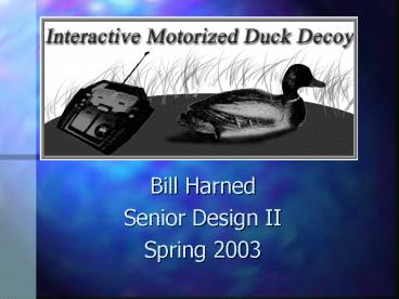
- Bill Harned
- Senior Design II
- Spring 2003
2
Team
- Team Leader
- Abdul Mohamed
- Team Members
- Kevin Brumfield
- Bill Harned
- Mark Williams
- Faculty Advisor
- Dr. Raymond Winton
- Sponsors
- Mike Gowan
- Michael Dean
3
Project Overview
- Problem
- Duck hunters must manually place duck decoys in
the water. - Requires the use of a boat.
- Decoys do not exhibit any lifelike appearance.
- Solution Provide a remote controlled duck decoy
with autonomous capability
4
Previous Project
- Design
- Two DC motors (H-Bridge)
- 9.6 V Rechargeable battery pack
- Operation at 27 MHz
- Features
- 10 hours of operation
- 45 yard range
- Tow 3 decoys
5
Previous Project
- Problems
- Straight Movement (Control)
- Battery Life
- Circuit Stability
6
Improvements
- Use of a single motor and rudder
- More than 10 hours of battery life
- Autonomous Movement
- Variable Speeds
- Operation at 75 Mhz
7
Transmitter Features
- Futaba FP-4NL
- Automated Route System
- Microcontroller PIC16F627
- R2R ladder
- Mode switch
- Reset button
- Four routes
- One user-defined route
- Emergency stop
- Range of 65 yards
8
Summary
9
Receiver Components
- Generic Decoy 10.7x5.8x6.2 in.
- Single DC Motor
- 20 turn
- 192 gcm torque rating
- Servo S3003
- 3.2 kgcm torque rating
- 8 mA current drain
- 7.2 V Rechargeable Battery
- Weight 3.2 lbs.
10
Summary
11
System Block Diagram
CH1
CH2
Transmitter Circuit
Mode Switch
Route Circuit
12 volts (8 AA batteries)
12
Pot Readings
Denotes the use of a speed controller which
neglects backward movement
13
Schematic
14
R2R Ladder Circuit (DAC)
15
Software Design
- Initialize register configurations
- Endless Loop (forever)
- Detect Digital Input (button press)
- if (button is true)
- latch binary input to output pins
- call delay routine (seconds)
- end if
- end loop
16
Software Flowchart
Ch1 2.5v, Ch2 2.5v
Route
1
2
3
4
Ch1 2.5v Ch2 3v
Ch1 2.5v Ch2 3v
Ch1 2.5v Ch2 3v
Ch1 2.5v Ch2 3v
8 second delay
8 second delay
1 second delay
8 second delay
Ch1 3v Ch2 3v
Ch1 2v Ch2 3v
Ch1 2.5v Ch2 2.5v
Ch1 2.5v Ch2 3v
4 second delay
4 second delay
i3?
1
0
17
Emergency Stop
- Stop/Reset Button
- If a route needs to be halted during an
active state, this feature will stop executing
the active route. - Take advantage of using the master clear enable
pin - Must use external clock
18
User-defined Route
- User can also record his/her own route
- Constraint is the total memory available in the
PIC for route storage - Record procedure records input for 15 seconds
- User can use play button to execute the route
19
Transmitter User Interface
- Front
- Power Switch
- 2 Control Switches
- Power LED
- Back
- Route buttons with labels
- Mode switch between automatic and manual
20
Current Drain of Transmitter
21
Summary
22
Cost per 1000 units
23
Summary
24
PCB Layout
- Add Picture
- PCB Dimensions
- 3.25x2.75x.6
- Receiver Box Dimensions
- 3.5x3.5x1.5
25
Summary
26
System Demo
- Video clip of the decoy executing the automated
routes.
27
Acknowledgements
- We would like to thank the following people
- Bill Buchanan
- Raymond Winton
- Billy Collier
- Way Beng Koay
- Michael Dean
- Mike Gowan
- MFJ Enterprises
28
Questions?
Recommended
CrystalGraphics Presentations


