
Project Background and Objective - PowerPoint PPT Presentation
1 / 12
Title:
Project Background and Objective
Description:
Device Fabrication. Silicon chip with microchannels and GMR sensors ... Design and operational variables will be optimized to detect and sort ... – PowerPoint PPT presentation
Number of Views:82
Avg rating:3.0/5.0
Title: Project Background and Objective
1
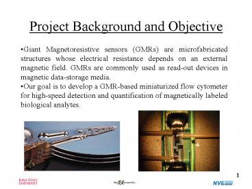
Project Background and Objective
- Giant Magnetoresistive sensors (GMRs) are
microfabricated structures whose electrical
resistance depends on an external magnetic field.
GMRs are commonly used as read-out devices in
magnetic data-storage media. - Our goal is to develop a GMR-based miniaturized
flow cytometer for high-speed detection and
quantification of magnetically labeled biological
analytes.
2
Principal Fluidic Diagram of a Miniaturized Flow
Cytometer
Magnetic label
- Magnetically-coupled biorecognition agents
(magnetic labels) bind to a specific analyte - Unreacted labels and labeled analyte are sorted
out based on differences in magnetophoretic
mobilities - Labeled-analyte flow stream is hydrodynamically
focused towards the GMR sensor to ensure
consistent detection
Sheath
Sample
3
Magnetic Sorter
- Electric current through buried current straps
induces local magnetic field gradient, and hence
magnetic force acting on magnetized objects
flowing along the channel.
Current straps
Magnetic sorter cross section and the resulting
horizontal component of the total magnetic field
4
Vertical Focusing of the Flow Stream Concept and
Architecture
Sheath flow
Magnetically labeled sample
GMR
Sheath flow
Sheath flow
Sample
Poly(dimethylsiloxane) (PDMS) lid with
microchannels
GMR sensor and microchannels on a silicon chip
5
GMR Sensor Architecture
- Two reference and two sensing GMRs configured as
a Wheatstone bridge
6
Device Fabrication
- The lid is fabricated in PDMS with the 360 µm
fluidic ports formed by using sacrificial plastic
inserts. After activating the chip and the lid
surface in oxygen plasma, the two are aligned and
bonded.
PDMS lid with microchannels and fluidic ports
Wire-bonding pads
Silicon chip with microchannels and GMR sensors
Fluidic port
7
Device Packaging and Testing
Ferrite flux guides
Coil
Sheath
Sample
Waste
Device on the magnetic excitation module, with
fluidic lines from syringe pumps
Micromagnetofluidic device wire bonded to a
printed-circuit board
8
Detection of Flowing Magnetized Entities Proof
of Concept
- Two immiscible fluids form alternate
picoliter-scale plugs at the junction
Perfluorodecalin (PFD) oil
Aqueous ferrofluid with fluorescein
GMR
T. Thorsen, R. W. Roberts, F. H. Arnold, and S.
R. Quake, Phys. Rev. Lett., 86, 4163 (2001) H.
Song, J. D. Tice, and R. F. Ismagilov, Angew.
Chem. Int. Ed. 42 (7), 768 (2003)
9
Ferrofluid Plug Formation
Ferrofluid
PFD
Ferrofluid
- Flow rate 1.0 µL/min
- Plugs formed at approx. 500 Hz
- Flow rate 0.2 µL/min
- Plugs formed at approx. 50 Hz
10
Ferrofluid Plug Formation
- Complex, periodic patterns formed at lower flow
rates (lt100 nL/min)
11
On-Chip Detection of Ferrofluid Plugs
Data collected at 10 Oe, bias voltage 1V, total
flow rate 0.1 µL/min
12
Conclusions and Prospects
- We have demonstrated direct sensing of magnetized
entities in a flow stream - Design and operational variables will be
optimized to detect and sort magnetically labeled
biological analytes
Acknowledgements
Porter Research Group NVE NSF XYZ On-a-Chip
Initiative William M. Keck Foundation DARPA
BioMagnetICs Institute for Physical Research and
Technology
Recommended
CrystalGraphics Presentations


