
Ethernet Technologies: 10Base2 - PowerPoint PPT Presentation
1 / 24
Title:
Ethernet Technologies: 10Base2
Description:
examines frame header and forwards frame based on destination MAC address. when frame is to be forwarded on a segment, uses CSMA/CD to access the segment ... – PowerPoint PPT presentation
Number of Views:184
Avg rating:3.0/5.0
Title: Ethernet Technologies: 10Base2
1
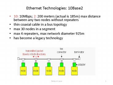
Ethernet Technologies 10Base2
- 10 10Mbps 2 200 meters (actual is 185m) max
distance between any two nodes without repeaters - thin coaxial cable in a bus topology
- max 30 nodes in a segment
- max 4 repeaters, max network diameter 925m
- has become a legacy technology
2
10BaseT and 100BaseT
- 10/100 Mbps rate latter called fast ethernet
- T stands for Twisted Pair
- Nodes connect to a hub star topology 100 m
max distance between nodes and hub - Hubs are essentially physical-layer repeaters
- bits coming in one link go out all other links
- no frame buffering
- no CSMA/CD at hub adapters speak CSMA/CD
- provides network management functionality
3
Gigabit Ethernet (IEEE 802.3z)
- 1Gbps data rate
- use standard Ethernet frame format
- star topology, allows for point-to-point links
(use switches) and shared broadcast channels (use
hubs) - Full-Duplex at 1 Gbps for point-to-point links
- in shared mode, CSMA/CD is used
4
Interconnecting LAN segments
- Hubs
- Bridges
- Switches
- Remark switches are essentially high performance
multi-interface bridges. - What we say about bridges also holds for switches!
5
Interconnecting with hubs
- Hubs are physical layer devices operate on bits
- Backbone hub interconnects LAN segments
- Extends max distance between nodes
- But individual segment collision domains become
one large collision domain - if a node in CS and a node in EE transmit at same
time collision - Cant interconnect 10BaseT 100BaseT
6
Bridges
- Link layer device operate on frames
- stores and forwards Ethernet frames
- examines frame header and forwards frame based on
destination MAC address - when frame is to be forwarded on a segment, uses
CSMA/CD to access the segment - can interconnect different LAN technologies
- plug-and-play, self-learning
- bridges do not need to be configured
7
Bridges traffic isolation
- Bridge installation breaks LAN into LAN segments
- bridges filter packets
- same-LAN-segment frames not usually forwarded
onto other LAN segments - segments become separate collision domains
LAN
8
Forwarding
- How do determine to which LAN segment to forward
frame? - Looks like a routing problem...
9
Self learning
- A bridge has a bridge table
- entry in bridge table
- (Node LAN Address, Bridge Interface, Time Stamp)
- stale entries in table dropped (TTL typically 60
min) - bridges learn which hosts can be reached through
which interfaces - bridge table initially empty
- when frame received, bridge learns location of
sender - records senders LAN address, arriving interface,
and current time in bridge table - delete an address in table if no frames are
received with that address as the source address
after some period of time
10
Filtering/Forwarding
- When bridge receives a frame
- index bridge table using destination MAC address
- if entry found for destinationthen
- if dest on segment from which frame arrived
then drop the frame - else forward the frame on interface
indicated - else flood
forward on all but the interface on which the
frame arrived
11
Bridge example
- Suppose C sends a frame to D and D replies back
with a frame to C.
- Bridge receives frame from C
- notes in bridge table that C is on interface 1
- because D is not in table, bridge sends frame
into interfaces 2 and 3 - frame received by D
12
Bridge Learning example
C 1
- D generates frame for C, sends
- bridge receives frame
- notes in bridge table that D is on interface 2
- bridge knows C is on interface 1, so forwards
frame to interface 1
13
Spanning Tree
- for increased reliability, desirable to have
redundant, alternative paths from source to dest - with multiple paths, cycles result - bridges may
multiply and forward frame forever - solution bridges determine a spanning tree by
disabling subset of interfaces
14
Some bridge features
- isolates collision domains resulting in higher
total max throughput - limitless number of nodes and geographical
coverage - can connect different Ethernet types
- transparent (plug-and-play) no configuration
necessary
15
Interconnection without backbone
- Not recommended for two reasons
- - single point of failure at Computer Science hub
- - all traffic between EE and SE must pass through
CS segment
16
Backbone configuration
Recommended ! With a backbone, each pair of LAN
segments can communicate without passing through
a third-party LAN segment
17
Bridges vs. Routers
- both store-and-forward devices
- routers network layer devices (forward packets
using network layer addresses) - bridges link layer devices (forward packets
using LAN addresses) - routers maintain routing tables, implement
routing algorithms - bridges maintain bridge tables, implement
learning and spanning tree algorithms
18
Routers vs. Bridges
- Bridges and -
- Bridges are plug-and-play
- Bridge operation is simpler requiring less
packet processing?high packet filtering and
forwarding rates - - All traffic confined to spanning tree, even
when alternative paths are available - - Bridges do not offer protection from broadcast
storms
19
Routers vs. Bridges
- Routers and -
- arbitrary topologies can be supported, cycling
is limited by TTL counters (and good routing
protocols)?packets can use the best path - provide protection against broadcast storms
- - require IP address configuration (not plug and
play) - - require larger packet processing time
- bridges do well in small (few hundred hosts)
networks while routers used in large (thousands
of hosts) networks
20
Ethernet Switches
- Essentially high-performance multi-interface
bridges - switches have large number of interfaces
- layer 2 (frame) forwarding, filtering using LAN
addresses - automatically build forwarding tables
- often individual hosts star-connected into
switch - Switching A-to-A, B-to-B, and C-to-C
simultaneously - Full duplex, no collisions!
- combinations of 10/100/1000 Mbps interfaces
21
Ethernet Switches
- cut-through switching frame forwarded from input
to output port without waiting for assembly of
entire frame - slight reduction in latency
- store-and-forward and cut-through switching
differ only when the output buffer becomes empty
before the entire packet has arrived
Preamble
DA
SA
type
Data
CRC
Store-and-forward sends after CRC
Cut-though forwards after DA
22
An Example LAN
Dedicated
Shared
23
Summary comparison
24
IEEE 802.11 Wireless LANs
- 802.11b
- operate at 2.4 GHz, 11 Mbps
- widely deployed
- 802.11a
- 5-6 GHz range
- up to 54 Mbps
- 802.11g
- 2.4 GHz
- up to 54 Mbps
- All have base-station and ad-hoc network versions
- All use CSMA/CA for multiple access
Recommended
CrystalGraphics Presentations


