
Solids Separation and Concentration of Shipboard Wastewaters and - PowerPoint PPT Presentation
1 / 2
Title:
Solids Separation and Concentration of Shipboard Wastewaters and
Description:
... This work is funded by the Strategic Environmental Research and Development ... Based on Navy needs, bilge water and black/graywater are highest priority. ... – PowerPoint PPT presentation
Number of Views:126
Avg rating:3.0/5.0
Title: Solids Separation and Concentration of Shipboard Wastewaters and
1
Solids Separation and Concentration of Shipboard
Wastewaters and Residuals by a High-Shear Rotary
Membrane System (HSR-MS)
Summary of Process/Technology
Introduction
- The HSR-MS system is a barrier technology that
uses ultrafiltration (UF) or microfiltration (MF)
membranes to separate the solute (e.g., solids,
oils, fibers, colloidal particles) from the
influent (Fig. 1). With proper membrane
selection/process operation, the effluent is
practically solids free. - During waste treatment solute builds up at the
membrane surface, increasing the resistance to
permeate flow. In conventional systems (e.g.,
tubular systems, Fig. 2.) solute buildup is
reduced by pumping the feed at high flow
rates/cross flow velocities so that the membrane
surface is scoured/cleaned. At high feed
concentrations/viscosities pumping becomes
difficult and most of the energy is wasted
because the entire feed volume is energized. - In the HSR-MS, which consists of stacked rotating
membrane disks, turbulence/shear is produced by
membrane rotation and the energy needed to clean
the surface is applied exactly where it is needed
(i.e., membrane surface, Fig. 3). - To further enhance turbulence/ shear at the
membrane surface, stationary turbulence promoters
are located on each side of the membrane disk. - The decoupling of the feed delivery/pressurization
from turbulence/shear promotion allows the
HSR-MS to produce highly concentrated wastes, be
operated at lower pressures, reduce boundary
layer compaction/pore plugging, increase membrane
life, and decrease cleaning frequency/residuals
production.
Navy ships generate a variety of wastes bilge
water, blackwater, graywater, shipboard
industrial wastes and solid residuals from
existing treatment systems. Many of the Navys
current waste treatment systems would benefit
from the efficient removal of solids. However,
available solids removal technologies have not
been particularly effective, necessitating the
development of improved solids removal
technologies. The High Shear Rotary Membrane
System (HSR-MS) has shown superior abilities to
separate and concentrate Navy and non-Navy
wastewater solids (e.g., oily wastes, underwater
hull cleaning sludge, non-skid deck cleaning
wastewater, tank car latex waste, metal hydroxide
suspensions). However, HSR-MS has been confined
to land-based applications where space is not a
critical design consideration. In this work
methods will be developed to increase the
permeate flux and modify the HSR-MS configuration
so that it can be placed shipboard.
Permeate
Objective and Goals
- The objective is to develop a robust shipboard
treatment system that can be used to treat a
variety of Navy solids-bearing wastewaters and
residuals. Specific goals are - Increase HSR-MS permeate flux/decrease system
size by - employing back pulsing and continuous
membrane cleaning. - 2. Increase the active membrane packing
density (active - membrane area/system footprint/space) by
using larger - diameter overlapping disks.
- 3. Conceptually design, fabricate and test a
shipboard HSR-MS - that incorporates back pulsing, continuous
membrane - cleaning, larger disks, and disk overlap.
- The shipboard HSR-MS will have an increased
waste - treatment throughput, a smaller
footprint/space requirements, - be potentially portable, and constructed of
lighter weight - and cheaper materials.
Feed (Cross-flow scours surface)
Pressure
Permeate
Fig. 3. High Shear Rotary Membrane
Fig. 2. Conventional Cross-flow Filtration
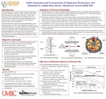
Disk Size (r)-Rotation Speed (?)-Pressure (P)
- Net transmembrane pressure (PNet-TMP) is a (r
?) - because Pback develops from rotating the
membrane - disk (Fig. 4)
- If r or ? are too large, a negative P can result
- Decrease in active membrane area
- Potential membrane destruction
- If lower ? is used, a larger disk is possible
- Decreasing ? increases CP/cake buildup
- Increase in membrane area is offset by lower J
- Increasing ? requires higher TMP
- UF/MF operate best at low TMP (minimizes
- compaction of solute layer)
- Need to operate with lower ? and TMP, but
- maintain high flux
- Need alternatives to reduce the solids layer
- resistance to allow the use of lower ? and
TMP - Back-pulsing
- Continuous mechanical cleaning
Benefits
- A shipboard HSR-MS can
- 1. More efficiently remove solids prior to
existing treatment - processes.
- 2. Directly replace problematic treatment
systems with a - more robust, higher efficiency system.
- 3. Concentrate sludge, waste oil and process
residuals. - The ultimate benefit to the DoD is a robust
barrier - technology that is easy to operate, not
labor intensive, is - capable of being cleaned in place, and can
withstand harsh - environments.
Fig. 4. Disk Size-Rotational Speed-Pressure
Relationship
2
Tracy Carole1, Momar Seck1, John Bendick2 and
Brian E. Reed3, 1NSWC Carderock Division,
Bethesda, MD, 2NAVICP, Mechanicsburg, PA,
3Department of Civil and Environmental
Engineering, Univ. of Maryland, BC
Testing Approach (Year 1 in Red)
Stirred Cell Test Results
Fig. 5. SCT Apparatus
Fig. 6. Example SCT Data for Black/Gray
Wastewater
Fig. 7. Summary of Black/Gray WW Tests - Avg. J
Permeate Turbidity
Task 1. Develop Synthetic Wastes
- Based on discussions with Navy personnel, four
wastes were identified - 1. Bilge water oily water, mixed detergent,
and particles - 2. Blackwater/graywater mixture 700-2,400 mg/L
total suspended solids (TSS) - 3. Biosolids 2-3 solids
- Plasma Arc Waste Destruction System (PAWDS)
wastewater quench water - from solid waste thermal destruction system
(inert ash at 6 g/L solids) - Based on Navy needs, bilge water and
black/graywater are highest priority.
Run Number
Fig. 9. Summary of Bilge Water Tests - Avg. J
Permeate Turbidity
Fig. 8. Example SCT Data for Bilge Water
- Summary of Blackwater/Graywater Stirred Cell
Tests (Figures 6 and 7) - SS-3 um had highest flux PTFE, SS-0.1 um, and
SS-0.5 um membranes had similar fluxes (J). - Turbidities decreased with run number and were
generally lower than 5 NTU. PTFE had higher - turbidities but may be due to poor fitting in
the stirred cell. - Only PTFE can be cleaned with 1 bleach
solution, significantly decreasing the cleaning
procedure. - Select SS-316-03 and PTFE for further study of
black/gray wastewater in Task 3. - Summary of Bilge Water Stirred Cell Tests
(Figures 8 and 9) - Flux PTFE gt SS-3 um gt SS-0.5 um gt SS-0.1 um
- Turbidities were similar at high run numbers
and were much lower than the feed turbidity. - Combination of 2 detergents and pH adjusted to
11.5 was an effective cleaning solution. - Select SS-316-03 and PTFE for further study of
bilge water in Task 3.
Task 2. ID and Screen Membranes
- Four commercially available membranes were
identified. - Membranes procured and are undergoing stirred
cell testing (SCT) using - the four identified wastes.
Task 3. Baseline HSR-MS Tests
- SpinTek constructed two automated pilot-scale
HSR-MS - units.
- Baseline testing on bilge and black/gray
wastewaters - will commence December 2009.
- Baseline data will be used to judge the
improvements - due to continuous mechanical cleaning and
back pulsing.
Stirred Cell Testing Procedure (Fig. 5 SCT
apparatus) 1. Clean water flux (CWF) on virgin
membrane to estimate membrane resistance. 2.
Waste treated by membrane at constant pressure,
permeate volume measured as function of
time. At end of run, composite permeate turbidity
measured. 3. Stirred cell flush with tap water,
cleaned according to membrane manufacturer
specifications, flushed again with tap water, and
CWF performed. 4. Repeat steps 2 and 3 several
times. 5. Results are presented as permeate flux
(volume permeate/membrane area-time, m3/m2-d)
versus time and CF composite permeate turbidity.
Acknowledgements This work is funded by the
Strategic Environmental Research and Development
Program (SERDP) and the Office of Naval Research
(ONR).
Recommended
CrystalGraphics Presentations


