
Siemens Integrated Safety - PowerPoint PPT Presentation
1 / 123
Title: Siemens Integrated Safety
1
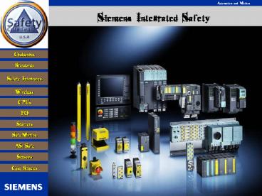
Siemens Integrated Safety
- Great Lakes Controls
2
Who am I ?
s
Siemens Energy Automation
Automation Motion Division
Production Machines Business Unit
200 Frank Slawson Rd
Oneonta, New York 13820
Steven Pickhardt
Tel 607 432 2543
Safety Product Consultant
Fax 678 297 8470
AMD Marketing
Steven.pickhardt_at_siemens.com
3
Safety at Work Nominees 4th place
4
Safety at Work Nominees 3rd place
5
Safety at Work Nominees 2nd place
6
And the winner is
7
Real Hazards
8
Real Hazards
9
The spirit of AD Safety Integrated
Accident prevention must not be interpreted as
the rule of law, but rather as a dictate of human
commitment and economic common sense.
(Werner von Siemens, 1880)
We start with a quote from the founder of
Siemens, that shows he cared about worker safety
in an era when most people did not!
10
Siemens Safety PLC Experience
- 1980 S5-110F
- 1988 S5-115F
- 1994 S5-95F
- 1999 S7-400F / PROFIsafe
- 2002 S7-315F / 151F
- / 416 F
- PROFIsafe
- 2003 S7-317 F / PROFIsafe
11
Siemens Safety Product Portfolio
- SIRIUS Safety Integrated
- Position switches , E-Stop ,
- Commanding Signaling
- Devices, Safety relays ASIsafe,
- motor starters
- SIMATIC Sensors
- Light curtains, Laser scanner
- and transceiver
- SIMATIC Safety Integrated
- Engineering, Controller, PROFIsafe, PROFINET,
F-Periphery - SINUMERIK / SIMOTION / SINAMICS Safety Integrated
- Integrated Safety, Safe standstill (SH),
- Safe operating stop (SBH), Safely-reduced speed
(SG)
12
Motivation
Dangers arising from malfunctions have to be
prevented before they occur.
13
Safety related applications sectors
- Cableways
- Lifting platforms
- Subway wayside door
- Signaling
- ...
- Burner control system
- Oil industry
- Chemicals
- ...
- Material handling
- Presses
- Processing machines
- Machine tools
- ...
No matter whether your safety requirements are
simple or highly complex, we are your worldwide
competent and reliable contact for
industry-specific safety concepts.
14
What challenges are you facing in your company?
15
32B Annual Costs of Industrial Accidents
Soft costs are 3 to 5 times the direct costs
- Direct Costs of Workplace injuries
- Lost compensation payments
- Medical and Insurance fees
- OSHA fines
9.2B
22.7B
- Lost Revenue
- Lost production revenue
- Downtime and repairs
- Training temp. employees
Source Controls Design, June 2006
16
Todays Safety Challenges CCCD
- Cost
- Compliance with Safety Codes Standards
- Complexity of Hardwired Solutions
- Diagnostics must provide swift troubleshooting
17
Our Customers Since 2002 Report
Market Drivers for New Safety Systems Include
- Faster Deployment
- Lower total cost of ownership
- Reduced Downtime
- Improved Operator Safety
18
The Changing Landscape of Safety
19
Users OEMs demand change in the safety arena
20
Compelling EventChanges the Safety Landscape in
the US
- Changing Safety Standards
- That was then NFPA 1997
- Where a Category 0 stop is used for the
emergency stop function, it shall have only
hardwired electromechanical components. In
addition, its operation shall not depend on
electronic logic (hardware or software) - NOW Since NFPA 79 2002 edition
- New wording allows PLC Use in Safety-Related
Functions - Software and firmware-based controllers to be
used in safety-related functions shall be listed
for such use.
21
Standards and certificates
- Fail-safe components comply with the highest
safety level - Factory Automation
- IEC 61508 up to SIL 3
- EN 62061 up to SIL 3
- EN 954-1 up to Category 4
- EN ISO 13849-1 up to PL e
- NFPA 79-2002 and NFPA 85
- UL 1998, UL 508 and UL 991
- Process Automation
- IEC 61508 (to SIL 3) and IEC 61511
- EN 954-1 (to Category 4)
- NFPA 79-2002
- and have certification from the TÜV of other
testing organization
22
International safety standards
- The applicable regulations and standards are
those in force at the location ofthe
installation or machine. - All countries follow the same basic principles in
their application. Europeanstandards and
regulations are recognized worldwide.
SIMATIC Safety Integrated is distributed and
accepted all the global markets
23
Transformation of Existing Standards
- IEC 61508 1998 / 2000
- recognized state-of-the-art technology
- for control and system manufacturers
- and structure-orientated
- EN 954-1 1996
- harmonized under EU Mach. Dir.
- only structure-orientated
- no programmable electronics
- still valid up to end of 2009
El. mech. devices
Excerpt
- ISO 13849-1 2006
- quantitative and structure- orientated
- for control integrators and manufacturers
- intended architectures for electronics.
- also for hydraulics, pneumatics
- IEC 62061 2005
- harmonized under EU Mach. Dir.
- for control integrators
- quantitative and structure-orientated
- uses PES acc. to IEC 61508
24
OSHA Employer Standards
- OSHA requires that each employer shall furnish to
each of his employees, employment and a place of
employment free from recognized hazards that are
causing or are likely to cause death or serious
physical harm to his employees. - OSHA Specifies minimal standards.
- OSHA uses industry consensus standards as well as
manufacturers instructions when investigating
accidents. - Manufacturers and employers should apply
consensus standards to help assure safety.
25
OSHA Federal Regulations 29
Code of Federal Regulations (CFR)
- Regulations Applicable to Machine Safeguarding
- General Care and Duty Clause
- 1910.212 General Machine Guarding
- 1910.217 Mechanical Power Presses
- 1910.219 Power Transmission
- 1910.147 Lockout/Tagout
- 1910.132 Hazard Assessment and PPE(Personal
Protective Equipment)
26
US Safety Requirements
Consensus Standards from recognized Agencies
Laws and Legal Requirements Fed/State
OSHA http//www.osha.gov NEC
Consensus / Professional Organizations ANSI http
//www.ansi.org NEMA http//www.nema.org NFPA ht
tp//www.nfpa.org RIA,AMT http//www.robotics.org
SAE http//www.sae.org
Trade Requirements CE
Department of Labor http//www.dol.gov/elaws
27
A Risk Analysis is now required in order to
determine your machines safety CAT level
Here are the simple steps involved
Based on these scenarios you can determine your
safety level between CAT1 to CAT 4 level is
safety enough
28
Considerations for Risk?
Reducing risks
Risk analysis
Changing the machine or process design
What?
Other measures to reduce risks
Against what?
Potential risks to people, processes and machines
Safety systems (Protective Measures)
Why?
Acceptable risk
Through what?
"Zero risk" cannot be achieved
29
Possible selection of the Categories in
accordance with EN 954-1
SP
SP - Starting Point
B, 1-4 Categories for safety-relevant parts
of controls
S - Severity of injury
Preferable categories for reference points
F - Frequency and duration
Possible categories requiring further measures
P - Possibility of avoiding the hazard
Over-dimensioned measure for the relevant risk
30
Minimum residual risk by applying suitable
protective measures to meet the Categories acc.
to EN954-1
31
Basic solution EN 62061 und ISO 13849
- A quantitative measure for safety-relevant
performance (Safety Performance) will be
introduced - EN 62061 Safety Integrity Level (SIL)
- ISO 13849-1 Performance Level (PL)
- EN 62061 and ISO 13849-1 take safety functions
into consideration - A certain hazard (as a result of the machine)
can be assigned to a defined safety function - The required Safety Performance can be
determined for a defined safety function
With SIL (EN 62061) and PL (ISO 13849-1) a clear,
hierarchic reference quantity is defined for the
Safety Performance.
32
Measure of the safety performance
- the required safety-related capability(safety
performance) depends on the risk - Previously category
- Solution-dependent
- No unique reference to the size of the risk
- Future SIL (Safety Integrity Level) / PL
(Performance Level) - Solution-independent
- Unique classification depending on the size of
the risk
SIL and PL can be represented on each other
33
Determination of the required Safety Integrity
Level (SIL) (IEC 62061)
34
Risk graph draft ISO 13849-1
Requiredperformancelevel PL
Low risk
a
P1
F1
P2
b
S1
Starting point for risk reductionestimation
P1
F2
P2
c
P1
F1
d
P2
S2
P1
F2
e
P2
High risk
Risk Parameters S Severity of injury F
Frequency and/or exposure time to the hazard P
Possibility of avoiding the hazard or limiting
the harm a,b,c,d,e Estimates of safety-related
performance level
35
Stop Categories from NFPA 79 IEC 61204
- Stop Category 0 Uncontrolled stop by
immediately removing the power to the machine
drive elements. - Stop Category 1 Controlled stop, the power is
only removed after the machine has come to a
standstill. - Stop Category 2 Controlled stop, where power is
still fed to the machine when it is at a
standstill.
36
Seamless Safety Integrated Into Automation Systems
37
Safety IntegratedThe integrated program for
safety technology
Detection and evaluation
Price
Complexity of Safety Application
ET 200 S F-CPU S7 300-F S7 400-F
ET200 SSIGUARD
ASIsafeSafety Monitor
3RA7 Safe load feeders
3TK2845Multi-function
3TK285.Safety Relay Contactor Relays
A complete product range for an optimal safety
concept
3TK28Relay
3TK2840Electronic
Functionality
38
Separate systems reduce productivity
Prior to 2002, U.S.A. required separation
PLC Control Technology
Control Cabinet
Safety Relays
PROFIBUS
39
Eliminate separated Safety Relay controls
PLC Control Technology
Control Cabinet
Safety Relays
PROFIBUS
40
Safety Integrated Provides many advantages
PLC Control Technology SAFETY
PROFIBUS SAFETY
41
Layers of Protection
Intelligent I/O
One Programming Software
Highly Reliable Network
Safety Rated CPU
42
Safety I/O level
Sensor supply
Two Processors at Module
Status
Data
00110001110001
CRC
Test signal
DecentralizedI/O
Safe Shut Down!
uP 2
CPUs Cross Check Each Other!
Failsafe I/O modules protect locally simplify
the design and wiring, Even if the PLC and
Network Fail, the I/O Module can go into Safety
Lockout
43
Certified Safety Output
Output signal
Two Processors at Module
Positive switched
One Output channel
Data
uP 1
001100011100
CRC
Read back
DecentralizedI/O
Ground Switched
uP 2
Read back
Input data
Output module includes input functions to test
Control components
Failsafe I/O modules protect locally simplify
the design and wiring, Even if the PLC and
Network Fail, the I/O Module can go into Safety
Lockout
44
Time redundancy and diversity instead of
physical redundancy
Controller
Failsafe CPU Program
- Time testing and diversity create tested Logic
- Standard-Operation for DATA represents the
program written in ladder logic - Diverse Operation for COMP created by compiler
requiring no programming - CPU-internal comparison at outputdriver allows
I/O to stop safety
Time Test
Build PROFISafe telegram
Example AND Instruction
Siemens achieves diversity on a single processor!
45
PTOPROFIBUS and PROFINET International
- The worlds oldest fieldbus organization
- Founded 1989
- The worlds largest fieldbus organization
- 1400 members
- The worlds leading fieldbus organization
- More than 18,800,000 nodes installed (3.4M in06)
- More than 2,500 devices types
- The worlds only global fieldbus organization
- 25 regional associations (PTO is one)
- 35 certified competence centers
- 8 certified test labs
- 9 certified training centers
- The worlds most experienced fieldbus
organization - Discrete (from 1989)
- Process (over 630,000 nodes)
46
Profisafe Communications Via PROFINET and PROFIBUS
47
PROFIsafe
How?
e.g., diagnostics
I/O
I/O
I/O
Safety Input
Safety Control
Safety Output
I/O or Controller
Safety-Layer
Safety-Layer
Safety-Layer
PROFINET
HTTPSNMP
PROFINET
HTTPSNMP
PROFINET
HTTPSNMP
PROFINET
HTTPSNMP
TCP/IP
RT
TCP/IP
RT
TCP/IP
RT
TCP/IP
RT
Ethernet
Ethernet
Ethernet
Ethernet
Black Channel" ASICs, Links, Cables, etc. are
not safety relevant
Non safety critical functions, like e.g. diagnosis
PROFIBUS or PROFINET
"PROFIsafe" Parts of the safety critical
communications systems Addressing, Watch Dog
Timers, Sequencing, Signature, etc.
Data Unit
Safety relevant, but not part of the
PROFIsafe-Profiles Safety I/O and the Safety
Control Systems
Fail-safe data
Standard data
48
PROFIsafeThe way to detect failure...
Remedy
Failure type
The measures shall be executed and monitored
inside one fail-safe unit
49
Competitive Comparison Industrial Ethernet
Safety Networks
50
S7 Distributed SafetySTEP 7 expansion for
factory automation
- S7 Distributed Safety
- for configuring the hardware and programming the
safety-related application with FBD and LAD in
the familiar STEP 7 environment. - The integral F library of commands with
off-the-shelf TÜV-certified programming
examples and function blocks individually
modifiable - EMERGENCY-OFF
- Two-hand control
- Muting
- Gate monitoring
- ....
51
Simple Safety program
Safety I/O and operating system keeps the Ladder
simple
52
Fail-safe communication via PROFIsafe- even
wireless
- Customer benefits
- Complex, delicately data link via replacing
collector ring with wireless - ?higher availability
- ?lower attendance costs
Client (W747-1RR)
53
Fail-safe communication via PROFIsafe- even
wireless
- Many participants move over access points
- Appliances
- e.g. electrical suspension track,
crane,automated guided vehicle system
- Customer benefits
- Advance of dependence at fast moving drag chains
- ?reducing costs
54
Fail-safe communication via PROFIsafe- even
wireless
- Bridging of problematic cable ways
- Appliances
- e.g. moveable communication partnerswithin a
big area like cranes, digger
- Customer benefits
- Freedom of movement
- Sensors connection in outdoor area via radio
- Saving of complex data cable solutions for
connection of moveable components
55
PROFIsafe Island within Security Zone
- Note Concept is covering satelite communication
also.
56
CAMotions Architecture
The availability of products to transmit Profinet
wirelessly fulfilled CAMotions desire to reduce
cabling costs by as much as 30 percent as well as
to shorten installation time and simplify
start-up.
57
Wireless HMI with Safety Built-in
Wireless (HMI)
Wireless (PROFIsafe)
Mobile Panel 277 IWLAN
Mobile Panel 277F IWLAN
Operator elements
Operator elements
Accessories
Charging station
Transponder
Battery
Planned for release Q1 2008
58
Siemen Safety Integrated Components
59
SIMATIC Safety Integrated controllersFor factory
automation
- S7-400F For high-end performance range
- CPU 416F-2
- MPI/DP DP(PROFINET via CP 443-1 Advanced)
- Multiprocessor mode possible
- gt 1000 F D-I/O-Channels
- S7-300F for the lower end to mid performance
range - CPU 317F-2DP
- MPI/DP DP
- 500 F D-I/O
- CPU 315F-2DP
- Interfaces MPI DP
- 300 F D-I/O-Channels
- ET 200S - For distributed applications in the
low-end performance range - IM 151-7 F-CPU
- MPI/DP
- 100 F D-I/O-Channels
- CPU 416F-3PN/DP
- MPI/DP Ethernet with integrated 2-Port-Switch
- Multi processor mode possible
- 11,2 MByte
- Integrated Web server
- gt 1000 F D-I/O channels
- CPU 319F-3PN/DP
- MPI/DP und DP Ethernet
- 1000 F D-I/O
- CPU 317F-2PN/DP
- MPI/DP Ethernet
- gt 500 F D-I/O
- CPU 317F-2DP
- MPI/DP DP
- gt 500 F D-I/O
60
SIMATIC Safety Integrated ControllerFor factory
automation
integrated
integriert
61
SIMATIC Safety Integrated ControllerFor factory
automation
integriert
62
Fail-safe ET 200S I/O Overview supported
busfield
- SIMATIC PROFIsafe-Module
- Parameterization using STEP 7
- UL listed
- IEC 61508 (up to SIL 3)
- EN 954 (up to Category 4)
- NFPA 79 2002, NFPA 85
- TÜV/BIA certification
Factory Safety
Process Safety
ET 200eco
ET 200eco
ET 200pro
ET 200M
ET 200M
ET 200S
ET 200S
63
Fail-safe ET 200S I/O Overview Functions
- SIMATIC PROFIsafe modules
- Parameterization using STEP 7
- UL listed
- IEC 61508 (up to SIL 3)
- EN 954 (up to Category 4)
- NFPA 79 2002, NFPA 85
- TÜV/BIA certification
Frequenzyconverter
Motorstarter
DI / DO
DO
DI
AI
64
Fail-safe ET 200M I/OThe range at a glance
- ET 200M
- For centralized expansion of the S7-300F
- For distributed expansion of ET 200S F-CPU,
S7-300F, S7-400F, S7-400FH - ? Supported safety related busses
- PROFIBUS via IM153-2 HF and IM153 FO HF
65
SIMATIC ET 200SFail-safe modules through
PROFIsafe
- Digital input modules4/8 F-DI PROFIsafe
- Digital output modules4 F-DO PROFIsafe
- F-relay modules for ET200S
- Cost-optimized SIL2 F-I/O modules for ET200S
- Power module for electronics modulePM-E F
PROFIsafe for safe shutdown of an internal and
an external load group up to 10 A, with 2
additional fail-safe outputs 24 V DC / 2A - PM-D F PROFIsafe power module
for safe selective shutdown of
motor starters F-DS and F-RS
66
Fail-safe ET 200pro I/OThe range at a glance
- ET 200pro
- For distributed expansion of ET 200S F-CPU,
S7-300F und S7-400F - ? Supported safety related busses
- PROFIBUS via IM 154-2 DP HF
- PROFINET via IM 154-4 PN HF
- Cabinet-free application due tohigh degree of
protection IP65/67 - High flexible by modular design
- Flexible typical connections
- Simple and user-friendly assembling
- High plant availability,e.g. by Hot Swapping
andpermanent wiring - Future-proof communication via PROFIBUS and
PROFINET
In preparation
67
Fail-safe ET 200eco I/OThe range at a glance
- ET 200eco
- For distributed expansion of ET 200S F-CPU,
S7-300F und S7-400Ffor a cabinet-free
distribution - ? Supported safety related busses
- PROFIBUS
68
SIMATIC ET200SF VFDs Starters
ET 200S
69
Safety Solution Local for standard(No Safety PLC
required
- Safety stops is at the Starter's Safety Power
Module. So, any CPU that can control the standard
starters. - High Feature head module is not required.
- EStops are connected to the PM-D Fx module
- Single Switching provided in each starter. So, if
the application is Category 3 or 4, an upstream
contactor is required. - Stop category 0 and 1 (guided shut
down with integrated
time delay. - Fulfills the requests of the highest safety
category 4 EN 954-1and
SIL 3 IEC 61508
For every safety application the right solution
70
Wiring comparison conventional solution / ET
200S Safety Solution Local
- Example 5 Motor starters Emergency stop Cat.4
EN954-1
Yesterday
Today
Constitution with safetyengineering since
today... (330 circuit connections)
... and today with ET 200S (50 circuit
connections)
2 Days
2 Hours
71
ET 200S Safety motor starter Solution Local
- Power module PM-D F1 (...F4)with integrated
safety relaysupply from - 24V-load voltage
- Electronics supply
- release circuit
- Emergency-stopcircuit
Connection module PM-XControlling and
integration of the loadfeeder contactor into the
release circuit
Auxiliary contact blocksIntegration of the load
contactor into the releasecircuit (F-Kit)
LEDssystem faultand status
Circuit diagrammotor starter
Infeed40A power bus (Standard motor starter)
Optionalterminals for PE and N conductors
Infeed50A power bus (HF motor starter)
72
SIMATIC ET 200S Motor starter Fail-safe
- Up to 80 less wiring
- Compact design for greatest safety
- Great flexibility whenoperating different
safetysegments - Easy to adapt tochanging safety environments
- Highest integration intoautomation environment
73
Motor Starter Fail-Safe
- A safe motor starter consists of a circuit
breakerwith shunt release, a contactor with
positivelydriven auxiliary contact and a safe
electronicevaluation circuit to detect faults. - In case of an EMERGENCY STOP, the power module
disconnects the supply voltage of the contactor
which then immediately drops out.If the control
of the contactor does not coincide with the
switching state of the positively driven
auxiliary contact, then the evaluation
electronics detects a fault and turns off the
circuit breaker. - In this case, the second tripping element is the
circuit breaker which is tripped by a safely
monitored shunt release when a failure occurs.
74
SIMATIC ET 200S Motor starter Fail-safe
PM-D F PROFIsafe
PROFIBUS DP PROFIsafe frame
S7-315F
Pos. switch
Manual / automaticswitchover
Em. off
Cable pull
Motor 1
Motor 2
- Shutdown via PROFIsafe" application
- Distributed monitoring of F sensor, signals are
transmitted via PROFIsafe to safety-related
controller - If necessary, switch off command is given in F
controller for safety segments 1 ... 6 of the - power module in the appropriate ET 200S station
- Fail-safe motor starters are then safely switched
off
Completely flexible motor starter assignment
within a PROFIBUS segment
75
SIMATIC ET 200S Motor starter Fail-safe
PM-D F X1 power module
Profibus DP
PLC
3TK28
Pos. switch
AS-i SaW monitor
Motor 1 2
Em. off
- "Switch off by external safety systems"
application - F sensor signals are monitored by external F
systems, e. g. safety relay or AS-Interface
Safety at work - Enable circuits of the external safety systems
are wired on each of the 6 safety segments - Fail-safe motor starters are then safely switched
off
Flexible combination of the motor starters with
external safety systems
76
Fail-safe ET 200S I/O Motor starters
- No external feeder contactor required
- Diagnostics (short-circuit, temperature)
- Parameterization functions for simple
commissioning
77
Almost no wiring
Conventional Motor Starter Today with ET200S
78
Ready for new Drive Functionality ...
Externalsafety technology
Drivecontrol
Drivecontrol
Integratedsafetytechnology
Externalsafety technology
Motor
Motor
Network With Profibus
79
SIMATIC ET 200S FCFrequency converter in
distributed I/O
SIMATIC ET 200S FC
- Universal solution for single drivesembedded in
the ET 200S distributed I/O up to 4 kW
80
Fail-safe ET 200S I/O Frequency converter
- Safe standstill
- Safe brake ramp
- Safely reduced speed
- Certified by German Institute for Occupational
Safety (BIA) and fulfill the requirements of
Category 3 acc. to EN 954-1and SIL 2 of IEC61508
81
Safe standstill
- Objective Protect the drive from starting
- The drive is brought into a safety-related
no-torque condition - The motor does not have to be electrically
isolated from the frequency converter to protect
against restarting
Classic design for the safe standstill function
using two contactors and a safety control
K1
Drive control unit
External components are not requiredSafety
Integrated
Safety control
Feedback
K2
The drive gating pulses are electronically
inhibited ? contactlessly for fast and defined
response time
82
ET 200S FC with integrated safety functions
Safe standstill
Safe braking ramp
Unique worldwide A motor encoder is not
required
Safely reduced speed
?Category 3 acc. to EN 954-1 SIL 2 acc. to IEC
61508
83
Safe braking ramp
- Objective Quickly stop the drive with safe
monitoring - Independent and continuous monitoring guarantees
the shortest response times when a fault occurs - Up until now unique A motor encoder is not
required
The control initiates the safe braking ramp
Safe stopping without requiring a motor encoder
84
Safely reduced speed
- Objective Reduce and monitor the drive speed
- Independent and continuous monitoring
- Up until now, unique A motor encoder is not
required
The control initiates safely-reduced speed
Safely-reduced speed without motor encoder
Safety at a minimum cost
85
Safety Integrated SINAMICS G120 General Purpose
Drive
86
Overview of G120 Power Modules
PM240 (3-ph. 400VAC 0.37 75kW CT(HO) / 90kW
VT(LO))
- Frame sizes A-F From 2.2kW integrated filter A (
only for TN line supplies ) - Integrated braking chopper
- IP20
- NEW Safety Integrated support
- TN-, IT- and TT grids
HO Highoverload LO Light overload
FSF 55-90kW
FSD 18.5-30kW
FSE37-45kW
FSA 0.37-1.5kW
FSB2.2-4kW
FSC5.5-15kW
87
SINAMICS G120 Control Units CU240S / CU240E
Picture of CU240S Typ
RS485 / USS (SUB-D)
88
Safety Integrated G120 Drive
Category 3 of EN954-1 and SIL 2 of IEC 61508
Additionally included Safe Brake Control (the
secure control of an external braking module).
Competition The Safe Stop and Safe Limited Speed
functions integrated in G120 are unique and
that worldwide!
89
New features of SINAMICS G120 STARTER
engineering tool
- User friendly integration of Safety Features
- Usabilityimprovements
- Fixedfrequencies has beenrevised
- Quickcommissioning andMotor ID have
beenrevised(try the new assistant)
STARTER V4.x commissioning software is available
as part of the PC connection set, it can be
downloaded from your SIEMENS representative
(Intranet) or ordered as a CD 6SL3072-0AA00-0AG0
90
SINAMICS S120 High Performance Drive
SINAMICS S120 The flexible, modular, high
performance Drive System
General Purpose Drives
High Performance Single Drives
Coordinated Drives
Servo Drives
- Pumps
- Fans
- Compressors
- Conveyors
- Centrifuges
- Traction drives
- Elevators
- Extruders
- Mixers
- Kneaders
- Motion control
- applications in
- Packaging machines
- Printing machines
- Handling
- Weaving machines
- ...
- Multi-motor
- drives in
- Paper machines
- Rolling mill lines
- Foil machines
- Synthetic fiber plants
- Harbor cranes
91
drive based Safety Integrated (dbSI) Safety
functions integrated in the drive
Safe Torque Off (STO)
Safe Torque Off (STO)
Safe Stop 1 (SS1)
Safe Stop 1 (SS1)
Safe Brake Control (SBC)
Safe Brake Control (SBC)
dbSI Basic Functions via onboard terminals
dbSI Extended Functions, via PROFIsafe or TM54F
Safe Stop 2 (SS2)
Safe Operating Stop (SOS)
Safely-Limited Speed (SLS)
from V2.5 SP1
Safe Speed Monitor (SSM) feedback signal n lt nx
Safety functions for drives according to IEC
61800-5-2
92
Controlling safety extended functionsintegrated
in the drive
Via safety-relevant communications with PROFIsafe
dbSI
F program
Sensor system
drive based Safety Integrated
Via terminals with TM54F
dbSI
Sensor system
Safety interconnection
93
Stopping in an emergency acc. to IEC 60204-1
n
Stop Category 0
? Line contactor open
Example application Stopping an extruder
n
t
Coast down
n
Stop Category 1
? Line contactor open
Example application Stopping a belt drive
n
Controlled stopping
t
No torque
n
Stop Category 2
Example application Hoist(the load does not sag)
Controlled stopping
n
t
Full torque
94
Safe stopping acc. to IEC 61800-5-2STO, SS1, SS2
n
Safe torque off initiated
Stop Category 0
n
Electrical isolation from the line supply is not
required!
Safe Torque Off
t
Safe Torque Off
n
Stop Category 1
Defined braking ramp
n
Safe Stop 1
t
Safe Torque Off
t
n
Stop Category 2
Defined braking ramp
n
Safe Stop 2
t
Safe Operating Stop
t
Full torque
95
Monitoring the braking phase Detecting drives
that accelerate out of control
- Safe acceleration monitor
- After the SS1 or SS2 extended function is
activated this function monitors the safe braking
of a drive - If the drive starts to re-accelerate this is
safely detected - Safety-relevant actual value sensing is a
prerequisite
Monitoring the braking phase (tolerance bandwidth)
Possiblefaultsituation
Fault detection and pulse cancellation (STO)
96
Safe Brake Control (SBC)
- Brake control direct on Motor Module
two-channel with monitoring - Can be activated in conjunction with STO and SS1
- Both DC 24 V and ground are switched
- Caution! Mechanical faults of the brake cannot be
detected
In the event of a single fault in the brake
control the brake remains fully operational!
Power Section
Control and Monitoring
DC 24 V Supply
24V
B
24V
Channel 1
M
Monito-ring
Diagnosis
M
B-
Channel 2
Motor with integratedbrake
U2 V2 W2
Motor Module
Load
Power Cable
Power Connector
97
Features of the stop functions integrated in the
drive STO, SS1, SS2
- When STO is activated the pulses are immediately
cancelled ? the drive coasts down in an
undefined fashion - When SS1 or SS2 is activated the drive brakes
along apermanently set ramp (OFF3) autonomously
These functions for safe stopping are suitable
for autonomous drives. They are only
conditionally suitable for stopping coordinated
drives.
98
Protection against hazardous motion
- Safe Operating Stop (SOS)
- Safe standstill monitoringof a drive that is
already at standstill - The drive provides full torque
- Safety-relevant actual value sensing is a
prerequisite
Standstill monitoringactivated
SOS activated
99
Protection against hazardous motion
- Safely-limited speed (SLS)
- Monitors configurable speed limit values (4
values are possible) - The limit value is monitored in both
directionsof rotation - Safety-relevant actual value sensing is
aprerequisite
SLSactivated
Response to an error STO, SS1, SS2 or SOS
(parameterizable)
Speed monitoring activated
n
nset
Speed limit (it is possible to toggle between
four values even while SLS is activated)
nmax_x
t
t4
100
Protection against hazardous motion
- Safe Speed Monitor (SSM)
- SSM supplies a safety-relevant output signal if
the drive falls below a defined speed limit value - There is no independent drive response if the
limit value is exceeded (only signal) - The limit value is monitored in both directions
of rotation - Safety-relevant actual value sensing is a
prerequisite
n
Application example A guard is released when nx
is fallen below
n x
t
SSM feedback signal
t
101
Features of the SOS and SLS safety functions
- SOS and SLS do not automatically influence the
drive speed - An autonomous response (e.g. STO) is only made
when a limit value is exceeded - The higher-level control must bring the drive,
within the set time, to below the limit value
(for SLS) or down to standstill (for SOS) - This allows coordinated axes to be ramped-down in
a controlled fashion
This is the reason that these functions are
suitable to stop coordinated drives in a
safety-relevant fashion
102
Commonality SIMOTION D and SINAMICs S120
Central control unit The control unit is the ONLY
difference between the various control systems.
Control Units SINAMICS CU320 SIMOTION D445 D4
35 D425 SINUMERIK NCU730 NCU720 NCU710
103
Safe Drives Functionality
104
The AS-Interface System
105
AS-Interface The Intelligent Alternative to
Conventional Wiring
Sensor
Sensor
Aktor
Actuator
Control cabinet-free flexibility with AS-i 1
instead of 1,000 cables!
106
AS-Interface Distributed Configuration Safety at
Work
Standard PLC andstandard master
Safety monitor
Safe emergency stop button
Safe module
Standard module
Safe light grid
AS-i power unit
Safe position switch
Safe light barrier
Standardmodule
107
Easy Grouping of Safety Signals with
AS-Interface Safety at Work
Standard-PLC andstandard-master
Safety monitor
Safety monitor
AS-i power unit
Safemodule
Safe emergency stop button
Safe emergency stop button
Safe emergency stop button
108
Major Components
Major Components
109
Wiring Example category 2
- For applications in compliance with Category 2,
both inputs at the safety module can be used. - This means that two electromechanical sensors in
compliance with Category 2 (positive opening
action contacts) can be operated.
Category 2 with safety-related modules
110
Wiring Example category 3 / 4
- For applications in compliance with Category 3/4
- A 2-channel input is used at the safety
module. - Inputs 1 is assigned a 2-channel sensor.
- Input 2 is sealed using an M12 cap, in order to
guarantee degree of IP67 protection.
Category 3 / 4 with safety-related modules
111
F-Link The missing link in the Safety
Integrated concept!
PROFIsafe
ASI(safe)
112
Safety Integrated Network Topology
(2)Connection of AS-i to PROFINET
HMI
SIMATIC S7-400F
SIMATIC S7-300F
SIMATIC ET 200
DP/AS-I F-Link
SIMATICET 200pro
Emergency Stop
SIRIUS Position-switch
SIRIUS
SIMATIC Lightcurtains
AS-Isafe Module
113
Other Safety Products Overview
114
SIRIUS Detecting Devices
3SE6 magnetic switches
Safety position switches Separate actuator
Hinge
Standard position switches
Mold. plastic IP66
Mold. plastic IP67
- Without locking
EN50047, molded plastic 31 mm or 50 mm
width Metal (M.2007) 2 or 3 contacts Snap-action
and slow
Molded plastic IP67 52 mm width 1 or 2
contacts Molded plastic IP66/67 EN50041
(M.2007) EN50047 3 contacts Metal IP66/67
EN50041 EN50047 (M.2007) 3 contacts
Switching magnets 1 NC/1NO 2 NC Safety Switc
hing device For 6 sensors
EN50041, metal 40 mm or 56 mm width Plastic
(M.2007) 2 or 3 contacts Snap-action / slow
For pivots andflaps 2 NC/1 NO
Snap-action Integrated inhingefor
doors 4 and 8 degrees 2NC/1NO Slow
30 mm width 2 and 3 contacts
- With locking
Molded plastic/ metal IP66/67, 54 mm width 2 x 3
contacts Locking force 1.500 or 2.500 N
Compact form with molded cable 2 contacts,
snap-action
Also with AS-Interface 3SF connection
115
SIRIUS-EMERGENCY-STOP Control devices
- EMERGENCY-STOP unit can be designed as mushroom
pushbutton or pull-wire switch - EMERGENCY-STOP control devices have to latch at
the time the contacts are positively opened.
116
Failsafe sensors
117
Applications light grids / transceivers
- Area / access protection
- No. of beams 2, 3 and 4
- Clearance 500, 400, 300 mm
- Range 0.8 - 18 m
- Area / access protection
- No. of beams 2, 3 and 4
- Clearance 500, 400, 300 mm
- Range 6 - 70 m
118
Applications
Horizontal hazardous zone safeguarding with
several protective fields
Horizontal hazardous zone safeguarding
Application with driverless transport systems
Collision protection for shunting trolleys
119
Operational Excellence through our Safety Core
Team
- The Safety Core team is made of Siemens AEs, ASs,
Key CoC technical representatives. Their function
is to provide a higher level of safety knowledge
base for our customers, STCs and sales people.
Some of there tasks are listed below - Higher Level of Safety Integrate knowledge.
- Quicker access to higher level support.
- Provide support for product rollouts.
- Have knowledge of safety technologies as well as
current safety standards. - Provide higher level of safety training to
technical support people and sales people. - Share best practice information.
- Support Safety Training Workshops
120
Totally Safety Integrated Automation
DP/DPLink
SIMATICS7 400F/H
SIMATIC S7 315F
ET200S PROFIsafe with motorstarters
ET200M/F
ET200S PROFIsafe
ET200S PROFIsafe
Sinamics
MICROMASTER
DP/AS-i Link
Proximity-typeprotectiveequipment
Operator panel
Safety door monitoring
SIGUARDLaser scanner
Fail-safeAS-i Module
Circuit breakers
SIGUARD Position switch
Proximity-typeprotectiveequipment
Safety door monitoring
121
OEM Case Study
- Case Erector Packaging Machine
- Discretely Wired Machine
- PLC
- 4 Electricians more than 1 week to wire
4 x 76 hours 304 hours - Startup 2 day for 2 electricians 2 x 2 x 8
32 hours - Category 3 safety system 4 x 8 32
hours -
- Total 368 hours
Source Pearson Packaging
122
OEM Case Study
Case Erector Packaging Machine Machine built
with distributed I/O and distributed safety I/O
PLC 2 Electricians 1 week to
wire 2 x 40 80 hours No junction
boxes No conduit No wire markers No wire
terminals Startup less then 1/2 day for 2
Electricians 2 x 4 8 hours
Category 3 safety system 2 x 4 8
hours Eliminate Conduit Significant Labor
Reduction Installation Hardware Panel Space
Total 96 hours
-26
Source Pearson Packaging
123
KUKA Reduces Cost Improves Safety
- Rod Brown, Controls Process Engineer at Kuka
Flexible Production Systems states savings of - 85 of conventional safety
- components
- 30 to 35 in labor costs
- 20 to 25 in reduced installation time
- additional reductions in panel size, floor
space, and - engineering effort
- Anticipated operating efficiencies include
- reduced down time due to
- improved diagnostics
- improved productivity due to
- increased up time
124
What Does This Do For You?
- Benefits
- Reduced Wiring
- 66 decrease in wiring
- Decrease footprint
- Increased Line Efficiency
- Increased reliability- MTBF
- Faster line changeover
- Faster troubleshooting
- Improved Engineering Efficiency
- Common Engineering Tools
- Tools for Validation Compliance
- Faster Commissioning
- Certified products (not application dependent
for basic safety functions) - Simplified machine checkout
Simplified Safety from Siemens
125
Thank You!
Recommended
CrystalGraphics Presentations


