
Clippers - PowerPoint PPT Presentation
1 / 10
Title:
Clippers
Description:
You have been previously shown a clipper. The half wave rectifier. ... SERIES CLIPPER - the diode is in series with the load. ... of the series clipper. ... – PowerPoint PPT presentation
Number of Views:5352
Avg rating:1.0/5.0
Title: Clippers
1
Clippers
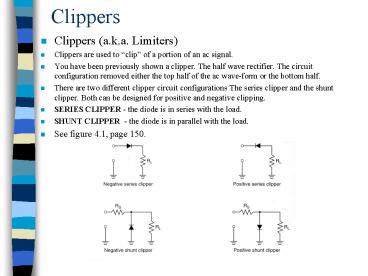
- Clippers (a.k.a. Limiters)
- Clippers are used to clip of a portion of an ac
signal. - You have been previously shown a clipper. The
half wave rectifier. The circuit configuration
removed either the top half of the ac wave-form
or the bottom half. - There are two different clipper circuit
configurations The series clipper and the shunt
clipper. Both can be designed for positive and
negative clipping. - SERIES CLIPPER - the diode is in series with the
load. - SHUNT CLIPPER - the diode is in parallel with
the load. - See figure 4.1, page 150.
2
Series Clippers
The operating characteristics of the series
clipper is exactly that the half wave rectifier.
See figure 4.2 below, page 151in your text. VL
Vin - 0.7 V
3
Shunt Clippers
The operating characteristic of the shunt clipper
is opposite that of the series clipper. When the
diode is forward biased in the series clipper it
produces an output to the load, when the shunt
clipper is forward biased it prevents the output
signal from being delivered to the load. The
opposite for both is true during the reverse bias
mode. See figure 4.3 below, page 152 of your text.
4
Shunt Clippers
During the portion of output signal delivery in
the shunt clipper circuit there is a voltage
divider effect due to the series current
limiting resistor. The resulting VL can be found
using this common divider formula. VL RL
x Vin RL Rs During the negative
half cycle of a negative shunt clipper, the diode
is forward biased, thus the load is held to 0.7 V
and the series limiting resistor voltage is Vin -
0.7 V. For a positive shunt clipper, the
opposite is true.
5
Biased (Shunt) Clippers
A Biased clipper has a dc supply proved at the
anode or cathode of the diode in order that we
may clip the wave-form a voltage levels other
than just that of the diode. See figure 4.9
below, page 155 of your text. Notice VB in
series with the diode. This provides a reference
voltage other than ground.
6
Biase (Shunt) Clippers
For the positive biased clipper, the input signal
is clipped at VB 0.7 V, where VB is any
selected dc level. If VB was 3 V, then the signal
would be clipped at 3.7 V. If VB was 7 V, then
the signal would be clipped at 7.7 V, etc.. See
figure 4.9a below.
7
Biased (Shunt) Clippers
For the negative biased clipper, the input signal
is clipped at -VB - 0.7 V, where -VB is any
selected dc level. If -VB was -3 V, then the
signal would be clipped at -3.7 V. If -VB was -7
V, then the signal would be clipped at -7.7 V,
etc.. See figure 4.9b below.
8
Summary on Clippers
Figure 4.11, page 157 of your text.
9
Clippers Applications
- To control transient (abrupt) voltage or current
spikes - Both input circuitry and outputs need protection
- ac power supplies
- digital inputs circuits
- circuits involving cemf
- motors, relay contacts
- To extract and transfer electrical information
- AM detectors
10
Series Clippers
Next
Recommended
CrystalGraphics Presentations


