
Encoding and Transmission Choices - PowerPoint PPT Presentation
1 / 21
Title:
Encoding and Transmission Choices
Description:
used on low speed links, e.g. serial ports. Problems: ... used for 10Mbps ethernet over coax and twisted pair ... not used with twisted pair due to high ... – PowerPoint PPT presentation
Number of Views:144
Avg rating:3.0/5.0
Title: Encoding and Transmission Choices
1
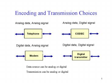
Encoding and Transmission Choices
Analog data, Digital signal
Analog data, Analog signal
digital
analog
analog
voice
CODEC
Telephone
Digital data, Digital signal
Digital data, Analog signal
analog
digital
digital
digital
Digital transmitter
Modem
Data source can be analog or digital Transmission
can be analog or digital
2
Encoding
- How do we encode the data for transmission so
that it can be recognized by the receiver?
Data 1 0 0 0 0 0 0 0 0 0 1 0 1
0
Sender
Transmission media
Receiver
1 wheres the clock? 0 0 1 0 1 0
how many 0 bits here?
3
Reception Problems
- Receiver must determine the start of each bit
period (clock synchronization). - Receiver must detect where each frame starts and
ends. - Signal contains noise
- thermal noise, impulse noise, delay distortion,
... - in general, higher transmission rate means more
noise
4
Desirable Features of Encoding
- Efficient use of bandwidth
- Clock recovery (synchronization)
- sender can recover timing of original signal
- Error detection
- some codes enable decoder to detect bit errors
(higher layers contain additional error
detection) - Error recovery
- after an error, can receiver find the start of
next frame?
5
Desirable Features of Encoding
- Minimize high frequency component
- lower frequencies mean less transmitted energy,
less radiated EMF in electrical systems, cheaper
hardware - Concentrate info in the middle of the transmitted
spectrum - distortion and interference are worse at edges of
band - No net d.c. component
- d.c. component requires direct physical
attachment of equipment for electrical
transmission. No d.c. means electrical isolation
can be done protects equipment, less
interference.
6
Digital Encoding Formats
0
1
0
0
1
1
0
0
0
1
1
NRZ
NRZI
Bipolar -AMI
Pseudoternary
Manchester
Differential Manchester
7
Spectral Distribution
1.5
B8ZS, HDB3
NRZ-L, NRZI
1.0
AMI, Pseudoternary
Manchester, Differential Manchester
Mean square voltage per unit bandwidth
0.5
0
0.5
1.0
1.5
Normalized frequency (f/r)
-0.5
- No d.c. component (energy at f 0)
- Efficient use of bandwidth small f/r
- Signal concentrated in center of band
Desirable Characteristics
8
Nonreturn to Zero (NRZ)
- 1 power on (signal)0 power off (no signal)
- used on low speed links, e.g. serial ports
- Problems
- lack of clock recovery during long string of 0 or
1 bits - has d.c. component
- baseline wander during long string of 0 or 1
bits
9
Nonreturn to Zero Inverted (NRZI)
- 1 change of signal level (on-off or off-on)0
no change of signal level - NRZI is an example of differential encoding
- used with with 4B/5B on fast ethernet
- fixes clocking problem for long string of 1 bits
- Problems
- lack of clock recovery during long string of 0
bits - has d.c. component
10
Manchester Encoding
- Always transition in middle of bit period0
low-to-high transition1 high-to-low transition - Transition at beginning of bit period when
necessary - used for 10Mbps ethernet over coax and twisted
pair - good clock recovery, good signal recovery, no
d.c. comp. - inefficient use of bandwidth 10Mbps ethernet
uses a 20Mbps signaling rate! Not used for fast
ethernet. - data-dependent high frequency component
11
Differential Manchester
- Mid-bit transition is used only for clocking
- 0 transition at beginning of bit period
(low-to-high or high-to-low, depending on
previous output level)1 no transition at
beginning of bit period - used in IEEE 802.5 Token Ring at 4Mbps and 16Mbps
- same properties as Manchester encoding, but
better signal detection and clocking in presence
of noise - inefficient use of bandwidth 2B signaling for a
data rate B
12
Bipolar-Alternate Mark Inversion
- Uses 3 signal levels V, 0, -V
- 0 no signal (0 voltage)1 alternating V and
-V - no net d.c. component (alternating V and -V)
- can detect some bit errors (consecutive V or -V)
- Problems
- loss of synchronization during long string of 0
bits - inefficient use of bandwidth with 3 signal
levels you could transmit log2(3) 1.58 bits of
information
13
Pseudoternary
- Same as Bipolar-AMI except reverses signaling
- 1 no signal (0 voltage)0 alternating V and
-V
14
Bipolar with 8-Zeros Substitution (B8ZS)
- Modification to Bipolar-AMI to eliminate string
of 0 bits - Replace any octet of all 0 (00000000)
with000-0- if previous non-zero signal was
000-0- if previous non-zero signal was - - This causes 2 code violations, so receiver knows
it is a substitution byte, not a transmission
error - good clock recovery
- most of the transmitted energy is in middle of
the spectrum no d.c. component - B8ZS is used with pulse code modulation (PCM) on
T1 lines (1.544 Mbps) B3ZS and PCM are used on
T3 lines.
15
B8ZS and HDB3
Bit value
Bipolar-AMI
B8ZS
HDB3
16
High Density Bipolar-3 Zeros (HDB3)
- Modification to Bipolar-AMI to eliminate zero
strings - Replace any 4 zero bits (0000)
withodd even 000 -00- if previous non-zero
signal was 000- 00 if previous non-zero
signal was - - Alternate (odd/even occurrence) between the two
- Each replacement causes one code violation
- good clock recovery most of energy is in middle
of the spectrum no d.c. component not as robust
as B8ZS - HDB3 is used on E-series public carrier lines (E1
is 2.048Mbps).
17
4B/5B
- Use 5 bit signals for each 4 data bits. The 5
bit sequences are chosen so that there are never
more than 3 consecutive zeros in the output
stream. When used with NRZI, will have at least
2 signal transitions in every 5 bits.
Input Output Input Output Other Output 0000 11110
1000 10010 Line idle 11111 0001 01001 1001 10011 S
TX 11000 10001 0010 10100 1010 10110 ETX 01101
00111 0011 10101 1011 10111 0100 01010 1100 11010
0101 01011 1101 11011 0110 01110 1110 11100 0111 0
1111 1111 11101
18
4B/5B with NRZI
- 4B/5B with NRZI is used for
- fast ethernet over fiber (100baseFX)
- FDDI
- 100Mbps Token Ring over fiber
- bandwidth is 125MHz for 100Mbps data rate
- not used with twisted pair due to high radiated
EMF
19
Bandwidth Comparison
- To send data at a rate D (bps) how much bandwidth
do the encoding methods use?
Encoding Used for Bandwidth Manchester 10Mbps
Ethernet, Token Ring 2D B8ZS, HDB3 T1, E1 lines D
log23 1.58D 4B/5BNRZI Fast Ethernet over
fiber, FDDI 1.25D
20
MLT-3
- MLT-3 uses 4B/5B followed by a 3 level
signaling0 no change in output level1
transition from 0 to -V next 1 returns to
0 next 1 transition to V next 1 return to
0 - used for 100baseTX, CDDI (100Mbps FDDI over
copper), and 100Mbps Token Ring on twisted pair - most of the transmitted signal energy is below
30MHz - no dc component can detect some bit errors
21
8B/10B
- Encodes 8 data bits using 10 signal bits, similar
to 4B/5B, but with these advantages - minimum deviation in number of transmitted 1 and
0 bits in any data sequence, using disperity
control - better error detection capability than 4B/5B
- used for Gigabit ethernet on fiber optic cable
and Fibre Channel - balance of transmitted 1 and 0 bits is important
to avoid data dependent heating of the laser,
which would increase the error rate