
Virtual Accelerator at JPARC 3 GeV Rapid Cycling Synchrotron - PowerPoint PPT Presentation
1 / 1
Title:
Virtual Accelerator at JPARC 3 GeV Rapid Cycling Synchrotron
Description:
K. Furukawa (KEK in Japan), S. Machida (CCLRC RAL in UK) ... To excite transverse beam motion by exciter. To detect the transverse beam position ... – PowerPoint PPT presentation
Number of Views:39
Avg rating:3.0/5.0
Title: Virtual Accelerator at JPARC 3 GeV Rapid Cycling Synchrotron
1
Virtual Accelerator at J-PARC 3 GeV Rapid Cycling
Synchrotron
H. Harada, K. Shigaki (Hiroshima University in
Japan), H. Hotchi, F. Noda, H. Sako, H. Suzuki,
Y. Irie (JAEA in Japan), K. Furukawa (KEK in
Japan), S. Machida (CCLRC RAL in UK)
1st Author Hiroyuki Harada, Email
harada_at_hepl.hiroshima-u.ac.jp
J-PARC
Abstract We have developed a Virtual
Accelerator at 3 GeV Rapid Cycling Synchrotron
(RCS) in J-PARC. It has a simulator of beam in
the complicated accelerator in order to simulate
behavior of beam and is put out under the control
server as well as a real machine. It enables to
do a dry run without beam, and consequently gives
a strong feedback for the RCS operation as a
commissioning tool. Therefore, we can examine the
control system for the real machine and practice
the commissioning of the real machine by using
the Virtual Accelerator. It is important to have
the tool based on beam dynamics for the
performance gain of an accelerator. Consequently,
it will lead a physics run for experiments of the
science at the J-PARC to success or a better run.
We present the concept of the control system
including the Virtual Accelerator and
construction of itself.
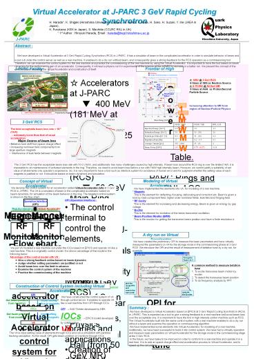
J-PARC Facility
Frontier of High Intensity
?Existing
?Under commissioning or construction
? Accelerators at J-PARC ? 400 MeV (181 MeV
at day-1) LINAC ? 3 GeV 25 Hz Rapid Cycling
Synchrotron (RCS) ? 50 GeV Main Ring
Synchrotron (MR) ? Facility at J-PARC ?
Materials and Life Science Facility (from 3 GeV
RCS) ? Nuclear and Particle Physics
Experimental Hall (from 50 GeV MR) ?
Neutrino Facility (from 50 GeV MR)
? 1MW _at_ 3 GeV RCS 6 times at ISIS as Neutron
Source ? 0.75 MW _at_ 50 GeV MR 5 times at AGS as
Proton/Second Particle Source Increasing
attention to MR from region of Nuclear-Particle
Physics
Materials-Life Sciences
This Project 3GeV
Power
?
Nuclear-Particle Physics
This Project 50GeV
?
1 MW
0.1 MW
Presented by Nagamiya Director at ATAC06
3 GeV RCS
The total acceptable beam loss rate lt 10-3
(1kW) ? extremely lower than that of usual
accelerators
- Major Source of beam loss
- Betatron tune shift from space charge effect
- Increasing nonlinear field components from large
aperture magnets - Interference of leak fields between magnets
Table. Parameters of J-PARC Rings and BNL AGS
The 3 GeV RCS has the acceptable beam loss rate
with 10-3 (1kW), and additionally has many
challenges caused by high intensity. If beam loss
around the RCS ring is over the limited 1kW, it
is impossible to do maintenance of activated
elements in the ring. Therefore, we need to avoid
beam loss before a run with 1MW high intensity
beam. However, we cannot justify a suitability of
set value of all elements only operators
experience. So, it is very important to have a
tool such as interlock system for avoidance of
human error and for judgment whether the setting
value of each magnets is justified or not. It
should be based on beam dynamics and simulation.
Modeling of Virtual Accelerator
Concept of Virtual Accelerator
We develop the control system for an accelerator
added Virtual Accelerator (VA) at 3 GeV RCS in
J-PARC. The VA is a simulator of beam in the
complicated accelerator based on beam dynamics,
for simulation of the beam behavior in the ring.
The targeted control system is shown in the flow
chart.
We have implemented the elements into VA, for
modeling of a real machine. Magnets This is
the element for deflecting, focusing, defocusing
and correction etc. Beam is given a kick by main
component field, higher order nonlinear fields,
leak field and fringing field. RF Cavity This
is the element for increasing and decreasing
energy. Beam is given an energy by gap voltage.
Exciter This is the element for excitation of
the beam transverse oscillation. Beam Position
Monitor (BPM) This is the monitor for getting
the transverse beam position and have a finite
resolution s.
- OPI (Operation Interface)
- The control terminal to control the elements,
such as Magnets, RF cavity and Monitors - EPICS (Experimental Physics and Industrial
Control System) - A set of Open Source software tools, libraries
and applications - Creation of distributed soft real-time control
systems for scientific instruments such as a
particle accelerators etc - Use of Client/Server and Publish/Subscribe
techniques to communicate between various
computers - The control server called IOCs including runtime
database - Input and Output to IOCs using the Cannel Access
(CA) network protocol.
A dry run on Virtual Accelerator
Flow chart of the control system for an
accelerator based on Virtual Accelerator
We have created the preliminary OPI to measure
the basic parameters and have virtually measured
the parameters on VA for the storage mode in the
commissioning phase at 3 GeV RCS. We introduce
the OPI and the result of measurement of betatron
tune by a dry run, for example.
We put VA modeled a real machine out under the
IOCs based on EPICS and operate VA like a real
machine. This is a originality control model. It
is shown advantage of this model in the following
below. Advantage of the control model with VA
Give a strong feedback online based on
beam dynamics Judge whether setting
parameters are justified or not Avoid
beam loss over the limit in advance
Examine the control system of the machine
Practice the commissioning of the machine
To log the Tune X Y
- A common method to measure betatron tune
- To excite transverse beam motion by exciter
- To detect the transverse beam position
- To do frequency analysis by FFT
plot the result FFT and search the tune peak
Construction of Control System including Virtual
Accelerator
operate the Exciter
OPI
We have constructed the control system of VA
through control server. It enables to operate VA
like a real machine from OPI through IOCs. OPI
? SAD TkInter developed by KEK IOCs ? EPICS
toolkit developed by collaboration VA ? SAD
developed by KEK
OPI for measurement of betatron tune
Get beam position from monitors
Input setting value to magnets etc
Summary We have developed a Virtual
Accelerator based on EPICS at 3 GeV Rapid Cycling
Synchrotron (RCS) in J-PARC. This is expected as
a tool to give a strong feedback to a real
machine and avoid beam loss over the acceptable
one. It is important to have the tool in high
intensity proton machine such as RCS. The Virtual
Accelerator built into the same control system
with a real machine enables to do a dry run
without a beam and examine the operation or
commissioning algorithm. We have implemented
some elements into Virtual Accelerator, for
modeling of a real machine. Additionally, we have
been successful to build it into control system.
We have had a virtually operation and measure
basic parameters on Virtual Accelerator for the
storage mode in the commissioning stage at the 3
GeV RCS. In the future, we have tasks to be
improved in order to conform to a real machine
and operate it in a real time. It is to add an
space charge effect and acceleration process to
Virtual Accelerator, and to speed up the
calculation.
IOCs
Input setting value to magnets etc
Get beam position from monitors
VA
A basic control system for Virtual Accelerator
The VA is input setting value of elements
through IOCs and run a simulation with particles
tracking calculation. As the result, OPI gets
beam position on monitors through IOCs.
Recommended
CrystalGraphics Presentations


